
Power module unit diagram of IGBT and fly-wheel diode

The electronic modules described serve various functions within power electronics and control systems.
The single switch module (a) is a basic building block for controlling power flow, typically used in applications requiring simple on/off functionality. The two-unit half bridge module (b) allows for the control of voltage across a load by switching two devices, effectively enabling bidirectional current flow.
The H bridge module (c) is essential for driving motors, as it allows for control of motor direction and speed by switching the polarity of the voltage applied to the motor. The asymmetrical H bridge module (d) provides similar functionality but is optimized for specific applications where one direction of current flow is more prevalent.
The three-phase bridge module (e) consists of six switching devices and is commonly used in three-phase motor drives and inverters, providing efficient power conversion and motor control. The chopping modules (f and g) are used for pulse-width modulation (PWM) techniques, which are crucial for controlling the output voltage and current in various applications, including DC-DC converters.
The three-phase bridge GD with chopping GAL (h) incorporates a braking chopper circuit, which is vital for regenerative braking applications, allowing energy to be fed back into the power supply during deceleration. The three-unit module (i) enhances flexibility and control by allowing multiple switches to be coordinated for complex power management tasks.
The single switch modules with series diodes (j, k, and l) are designed to prevent reverse current flow, thus ensuring protection of the circuit components. The collector end series diode (j) and emitter end series diode (k) configurations provide distinct advantages depending on the specific circuit design requirements. The two-unit module with a series diode (l) offers additional redundancy and reliability in applications where disconnecting switches are necessary for safe operation.
Overall, these modules are integral to modern electronic systems, facilitating efficient power management, control, and protection in a wide array of applications.Is single switch module; (b) is two unit (half bridge) module; (c) is H bridge (single phase bridge) module; (d) is asymmetrical H bridge module; (e) is three phase bridge (six unit or inverter bridge) module; (f) is chopping module (g) is chopping module (h) is three phase bridge GD add chopping GAL (braking chopper circuit) module; (i) is three unit module, consists of three group switch; (j) is single switch add collector end series diode ( negative direction disconnecting switch) module; (k) is single switch add emitter end series diode (negative direction disconnecting switch) module; (l) is two unit module, with series diode (negative direction disconnecting switch). 🔗 External reference
Related Circuits
This is a schematic diagram of a stereo audio amplifier for a car. The circuit is powered by a single IC, the TDA1553, along with some external components. This IC is designed to manage the stereo car audio system....
The RF power amplifier circuit described here utilizes the transistors 2SC1970 and 2N4427. This FM RF amplifier operates within the frequency range of 88-108 MHz, delivering an output power of approximately 1.3W from an input driver of 30-50mW. The...
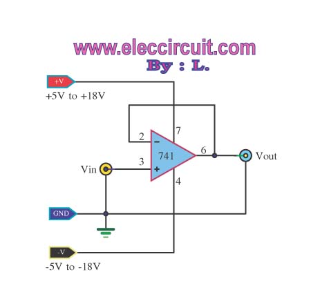
The buffer operational amplifier (op-amp) circuit is utilized for coupling two circuits together. It functions as a unity gain follower, also known as a voltage follower, which is employed to transfer or replicate a voltage from one circuit to...
A circuit is being designed for a DC motor utilizing the following components: 1 x 7805 voltage regulator and 2 x 2N2955 transistors, which are to be paralleled to increase current capacity. The proposed circuit will employ a 7805 voltage...
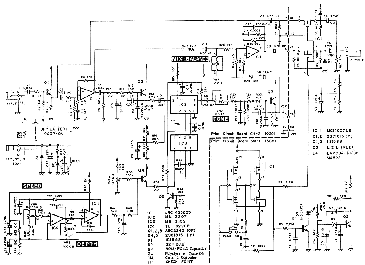
The Pearl CH-02 Chorus is a discontinued pedal known for its exceptional sound quality. It features four knobs: DEPTH, SPEED, TONE, and MIX BALANCE. The TONE knob specifically adjusts the tone of the effect sound, while the MIX BALANCE...
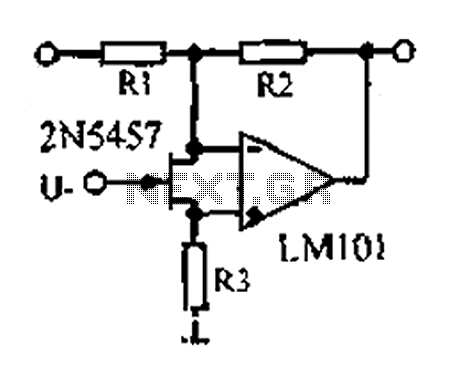
A 1.53 voltage-controlled gain amplifier (VGA) utilizes a FET connected between the two inputs of the operational amplifier (op-amp) as a voltage-controlled resistance. The resistance changes linearly with voltage and varies from several dozen square ohms, exhibiting excellent control...