
RF Amplifier circuit with 2SC1970 2N4427 Schematic Diagram

For effective operation of the RF amplifier utilizing the 2SC1970, it is recommended to employ a power meter, watt meter, SWR meter, or RF field strength meter. The circuit is capable of functioning across the entire frequency spectrum of 88-108 MHz and can achieve considerable radiation distances. During the tuning process, it is advisable to connect a 50 Ohm dummy load to the output. Additionally, a variable resistor (VR) should be incorporated to adjust the input signal level, ensuring it remains within the specified range of 30-50mW to prevent over-modulation.
The RF power amplifier circuit featuring the 2SC1970 and 2N4427 is designed to provide reliable performance in FM transmission applications. The choice of transistors is crucial, as the 2SC1970 is known for its high gain and efficiency, making it suitable for RF amplification tasks. The 2N4427, on the other hand, serves as an effective driver, ensuring that the input signal is adequately amplified before reaching the main power amplifier stage.
In constructing this circuit, careful attention must be given to component selection, layout, and grounding to minimize noise and interference. The circuit should be housed in a shielded enclosure to prevent external RF interference, which can affect performance. Adequate heat dissipation measures should also be implemented to manage the thermal output of the transistors, ensuring long-term reliability and stability of the amplifier.
Overall, this RF power amplifier design serves as a robust solution for FM transmission within the specified frequency range, providing significant output power while maintaining signal integrity. Proper tuning and adjustment techniques are essential for achieving optimal performance and ensuring compliance with regulatory standards for RF emissions.RF power amplifier circuit of this work is based on the transistor 2SC1970 and 2N4427. The set output power of 88-108 MHz FM RF Amplifier With 2SC1970 is about 1. 3W and the input driver is 30-50mW. RF driver amplifier circuit uses a 2N4427 and its power amplifier using a transistor 2SC1970. At the time of the amplifier circuit tuning FM 88-108 MHz RF Amplifier With 2SC1970 should use the power meter / watt meter or SWR or RF field can also use the meter. RF amplifier circuit can work from the frequency of 88-108 MHz. Circuit of 88-108 MHz FM RF Amplifier With RF 2SC1970 can radiate far enough. At the time of tuning you should use a 50 Ohm dummy load. For the input signal should be installed to regulate the VR level so as not to over-modulation (30-50mW).
You are reading the Circuits of RF Amplifier circuit with 2SC1970 2N4427 And this circuit permalink url it is 🔗 External reference
Related Circuits
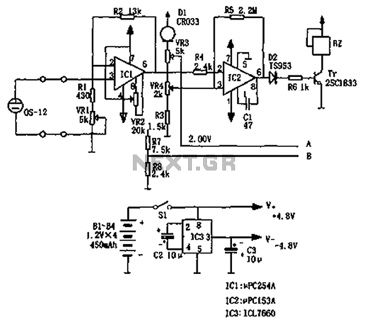
The circuit principle involves an oxygen sensor circuit utilizing the OS-12, a DC amplifier IC1, an A/D converter IC4, a liquid crystal display F2100-34PI, a voltage comparator IC2, and a positive and negative power converter IC, among other components....
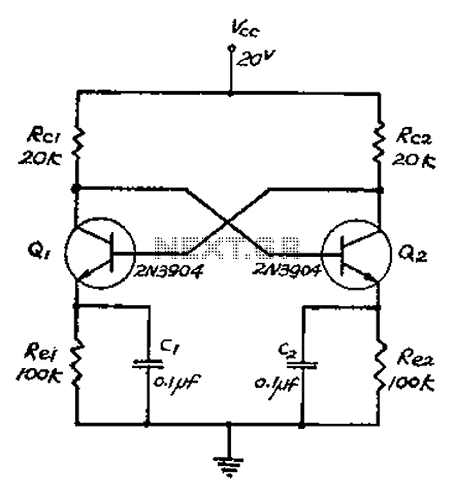
The collector and base-emitter bias of the transistor are directly coupled to each other. Each transmitter circuit controls the capacity conversion function. The emitter generates a triangular wave. The two transistors are not continuously in an active state. Instead,...
Power amplifier circuit diagram using the IC TLE2141C. The TLE2141C is a low-noise, high-voltage, high-slew-rate operational amplifier with a frequency response of 30 Hz. The TLE2141C operational amplifier is designed for applications requiring high precision and low noise, making it...
The schematic diagram has been modified to include a 220µF smoothing capacitor connected between the base of transistor Q1 and ground. This addition effectively mitigated the issue of relay chatter, which involved rapid on/off switching at light levels. The...
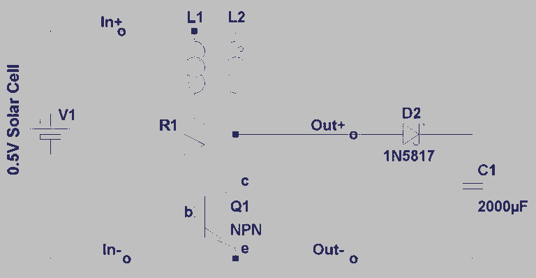
A steam engine-powered carousel project that utilizes the Joule Thief circuit. This project combines the classic charm of a steam engine with the innovative Joule Thief circuit, creating a unique carousel that operates efficiently. The steam engine serves as the...
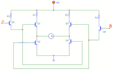
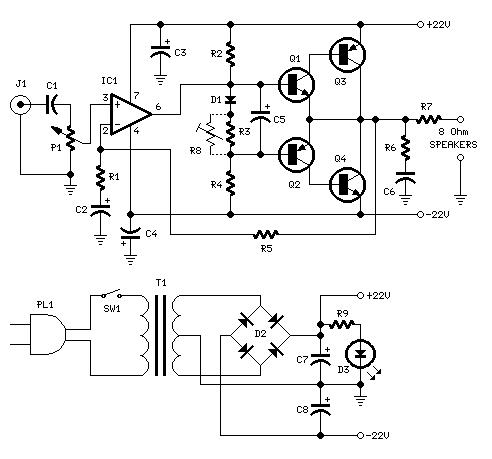
The transistors Q1, Q2, Q3, and Q4 form a bridge circuit. These are typically power transistors designed to handle high current. Transistors Q5 and Q6 drive the bridge. When input A is set high and input B is set...