
Darkroom timer

The darkroom timer/controller circuit is designed to facilitate precise control over photographic printing processes. The heart of the system is the 4-digit common-cathode LED display, which provides clear visibility of the timing settings in low-light environments. The digit driver interfaces with the display to convert digital signals into a format suitable for driving the LEDs, ensuring accurate representation of the countdown or elapsed time.
The time base is derived from the 50/60 Hz AC line frequency, which is shaped using a rectifier and a timer IC, such as the 555 timer, configured in monostable mode. This approach ensures a stable and reliable timing reference. The DPDT switch allows the user to select between two timing resolutions: 0.1 seconds for fine-tuning and 1 second for standard timing operations. This switch not only alters the timing intervals but also adjusts the decimal point's position on the display, providing intuitive feedback to the user.
The two AC outlets are strategically designed to control the enlarger and the safe light. The enlarger outlet is activated during the printing process, while the safe light outlet remains energized when the enlarger is off. This feature prevents accidental exposure of light-sensitive materials. The switching mechanism can be implemented using relays or solid-state devices, ensuring reliable operation under varying loads.
The buzzer, functioning as an alert mechanism, is integrated into the circuit to signal the completion of the timing cycle. Utilizing a self-contained oscillator design, the buzzer operates on a DC drive, offering a straightforward implementation that minimizes component count while ensuring effective auditory feedback.
Overall, this darkroom timer/controller circuit provides essential functionality for photographers, allowing for precise timing control in the darkroom environment while ensuring safety and usability.The darkroom timer/controller uses few external components: a display, a digit driver, keyboard, and output switching devices. A 4-digit common-cathode LED display is desirable for dark room environments. The time base is provided by shaping up the 50/60 Hz ac line. A DPDT switch (Si) is used to select a resolution of or 1 seconds and to simultaneously move the decimal point
Timer/ controller has two switched ac outlets, one for the enlarger and one for the safe light. They are the complements of each other in that the safe light is on when the enlarger is not active and is off when the enlarger is printing. The buzzer is of the self-contained oscillator variety and operates with dc drive.
Related Circuits

This door minder electronic project is based on a 555 timer circuit and utilizes an infrared (IR) beam to monitor doorways, passageways, or any other designated area. When the IR beam is interrupted, a relay is activated, which can...
This timer was designed for people wanting to get tanned but at the same time wishing to avoid an excessive exposure to sunlight. A Rotary Switch sets the timer according to six classified Photo-types. A Photo resistor extends the...
A simple metal detector circuit can be implemented using a 555 timer chip. The schematic diagram illustrates that this project requires only a few external electronic components. The metal detector circuit utilizing a 555 timer operates in astable mode, generating...
Pulse width modulation (PWM) is a technique to control analog circuits with a digital output. PWM is used in many applications, especially to control light intensity and speed on motors. A PWM circuit makes a square wave with a...
This 555 timer circuit toggles a relay when a button is pressed. Pins 2 and 6, the threshold and trigger inputs, are held at half the supply voltage by two 10K resistors. When the output is high, the capacitor...
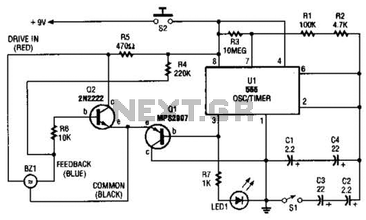
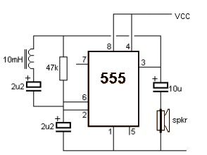
The electronic darkroom timer is constructed using a 555 oscillator/timer, a pair of general-purpose transistors, a buzzer, and an LED. The 555 timer (U1) is set up as an astable multivibrator, functioning as a free-running oscillator. The frequency of...