
Relay Driver

Relays are electromechanical devices that utilize an electromagnetic coil to mechanically operate a switch. The fundamental operation involves energizing the coil, which generates a magnetic field that attracts a movable armature. This movement either opens or closes the contacts within the relay, allowing or interrupting the flow of current in the circuit.
The design of a relay typically includes several key components: the coil, the armature, the spring, and the contacts. The coil is wound from insulated wire and is responsible for generating the magnetic field. The armature, often made of ferromagnetic material, is pivoted and held in place by a spring when the coil is not energized. When current flows through the coil, the magnetic field overcomes the spring tension, causing the armature to move and change the state of the contacts.
Relays are available in various configurations, including normally open (NO) and normally closed (NC) types. NO relays allow current to flow only when the coil is energized, while NC relays permit current to flow when the coil is de-energized. This versatility makes relays suitable for a wide range of applications, including automation systems, motor control, and signal switching.
One of the primary advantages of relays is their ability to isolate different sections of a circuit. This isolation protects sensitive components from high voltages or currents that may be present in other parts of the system. Additionally, relays can handle high inrush currents and provide a degree of electrical noise immunity.
Despite the rise of solid-state devices, relays remain relevant due to their simplicity, reliability, and ability to operate in extreme conditions. They can be found in various environments, from industrial machinery to household appliances, underscoring their enduring significance in electronic design.Relays have been around for a long time and though often now replaced with solid state switches, they have unique properties that make them more robust tha.. 🔗 External reference
Related Circuits
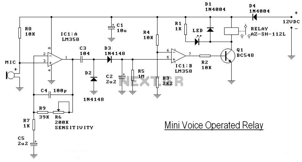
This circuit diagram represents a voice-operated relay. It functions similarly to a sound-activated switch circuit, which toggles the switch on and off (connects and disconnects) based on sound input. The output switch of this circuit is AC. The voice-operated relay...
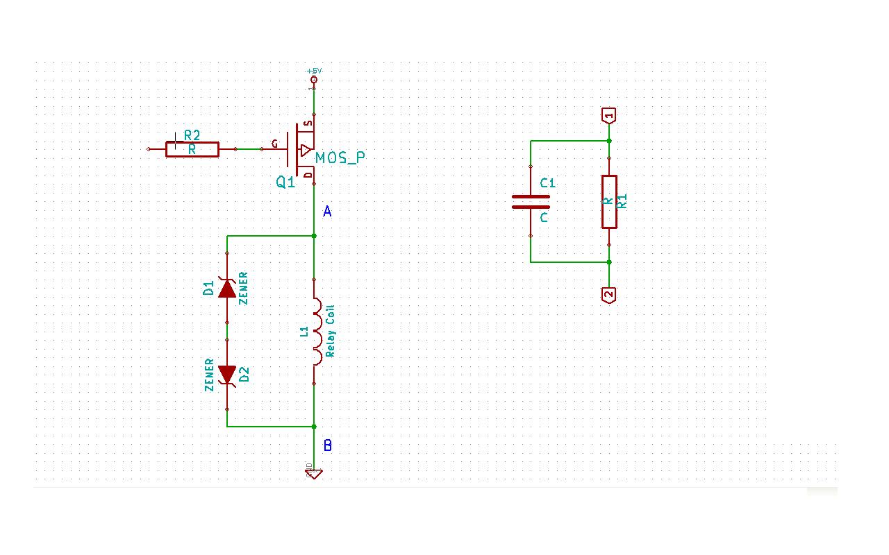
Although this may be a basic question, there is still some struggle with it. In this schematic, two zener diodes D1 and D2 are connected back-to-back across relay coil L1. The breakdown voltage (BVds) is -30V for Q1. The...
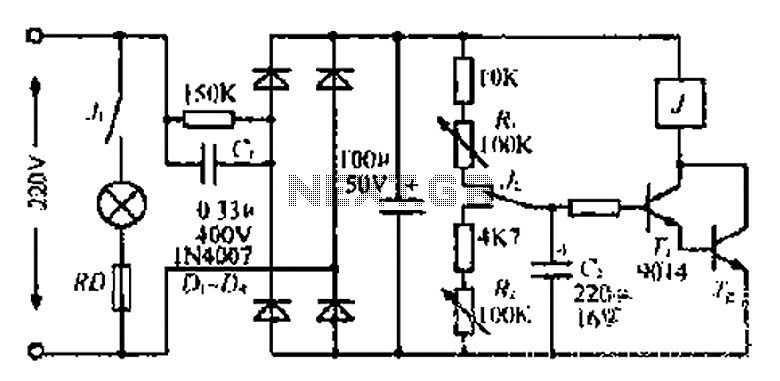
220V mains electricity is sent through a 0.33 µF capacitor (Ci) and a 50 kΩ resistive drop. A bridge rectifier composed of diodes D1 to D4 converts the AC voltage to DC. After passing through a 100 µF capacitor...
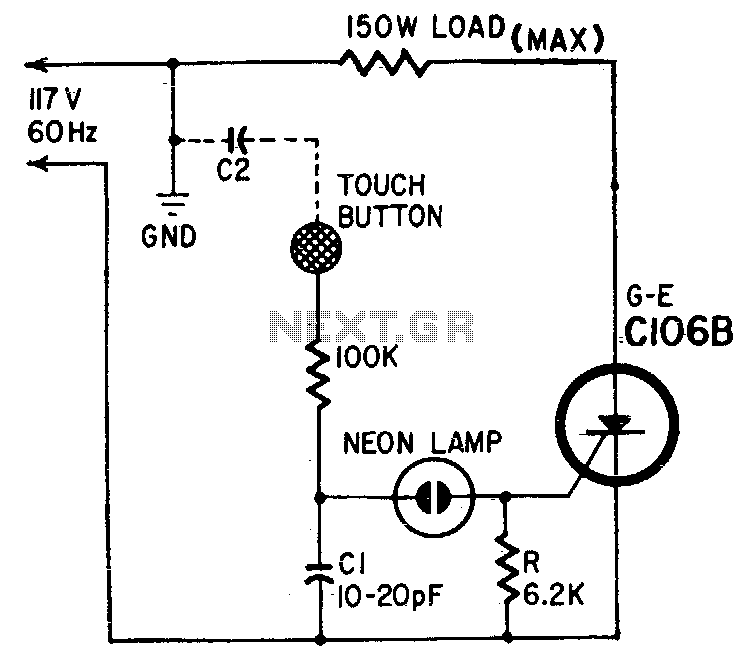
Capacitor Cl and body capacitance (C2) of the operator form a voltage divider from the hot side of the AC line to ground. The voltage across Cl is determined by the ratio of Cl to C2. A higher voltage...
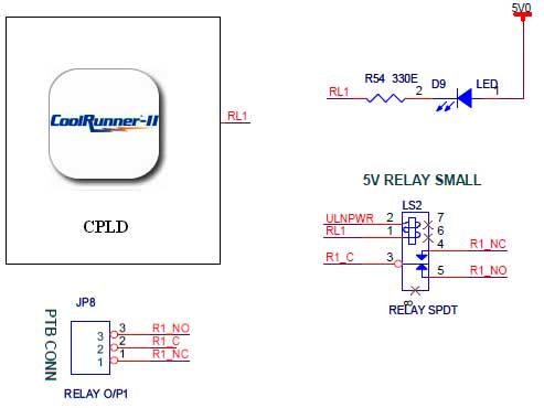
The CoolRunner-II board features external 5V relay interfacing, as indicated in the accompanying figure. The ULN2803 is utilized as a driver for the CPLD I/O lines, with the driver outputs connected to the relay modules. A PTB connector is...
The output cable from my 20 MHz function/sweep generator dangled over the side of the workbench, the alligator clip hovering over the floor. Deeply engrossed in a project, I moved the power strip on the floor a little closer...