
SensorCircuit Of Automatic Room Lights Based On The CD4017 IC

The automatic room light circuit utilizes the CD4017 decade counter IC, which is designed to count pulses and drive multiple outputs. In this application, it functions as a control mechanism for the lights based on ambient light levels detected by the LDRs. The LDRs are positioned strategically to detect changes in light intensity; when the ambient light falls below a certain threshold, the resistance of the LDRs increases, triggering the circuit to activate the lights.
The circuit typically includes a comparator, which can be implemented using an operational amplifier (op-amp) or a simple transistor-based design. The output from the LDRs is fed into the comparator, which compares the voltage level against a reference voltage. When the voltage from the LDRs drops below the reference level, the comparator output changes state, signaling the CD4017 to activate the connected lighting load.
In addition to the basic components, the circuit may include a relay or a transistor to handle the higher current required by the lights, ensuring safe operation without damaging the sensitive IC. The circuit can also be equipped with adjustable resistors to fine-tune the sensitivity of the LDRs, allowing for customization based on the specific lighting conditions of the environment.
Overall, this automatic room light circuit provides an efficient solution for lighting control, enhancing convenience and energy savings by ensuring that lights are only activated in response to the presence or absence of natural light.The following circuit shows about Sensor Circuit Diagram Of Automatic Room Lights. This circuit based on the CD4017 IC. . Features: uses two LDRs, .. 🔗 External reference
Related Circuits

The automatic fan controller circuit depicted in the schematic features two comparators with distinct triggering points that can be adjusted independently. LM135 or... The automatic fan controller circuit is designed to regulate fan operation based on temperature variations. It employs...
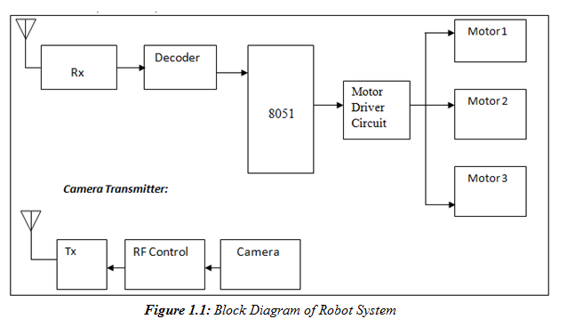
A prototype model of an agriculture-based robot has been developed to address the challenges faced by farmers who have traditionally relied on manual labor for cultivating their lands. The increasing urbanization has led to a shortage of labor, as...
This project automates home appliances via a Bluetooth-enabled PC. A USB Bluetooth adapter is utilized on the PC side, while a Serial Bluetooth module is employed for communication. This project involves the integration of a Bluetooth-enabled PC with home appliances...
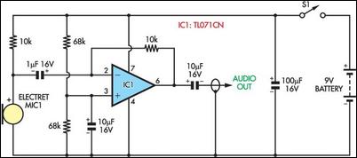
A wife was working on a doctoral dissertation that involved fieldwork, specifically personal interviews in various settings. The challenge was to find a suitable technical solution for recording these interviews. Passing a tape recorder or microphone back and forth...
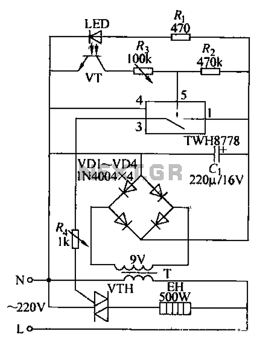
Bathroom automatic hand dryer circuit. The circuit features an LED and a photosensitive transistor (VT) that together form an infrared opto coupler, serving as a signal sensing mechanism. The control element is a 1WH8778 switch integrated circuit. When hands...
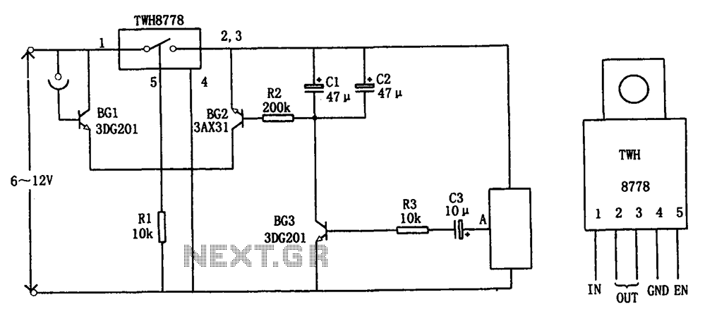
The circuit illustrated in FIG X pertains to automatic circuitry for US recorders. It primarily utilizes a new power switching device, TWH8778, which simplifies the design and eliminates the need for extensive debugging. The TWH8778's configuration and pin functions...