
Three single junction transistor time relay circuits

The three single-junction transistor time relay circuits are designed to provide a reliable timing function through a combination of exponential and pulse charging methods. The first stage of the circuit employs unijunction transistors (UJTs), which are known for their ability to generate precise timing signals due to their unique characteristics in switching and controlling current flow. In this configuration, capacitor C1 is charged exponentially, which allows for a gradual increase in voltage until a predetermined threshold is reached, triggering the next stage of the circuit.
The second stage, utilizing a different unijunction transistor (VT2), is responsible for a more abrupt change in voltage across capacitor C2. This stage's pulse charging approach ensures that once the capacitor reaches a certain voltage level, it can rapidly discharge, providing a quick response suitable for applications requiring immediate action after a delay. The combination of these two stages effectively creates a two-stage relaxation oscillator, where the total delay time is determined by the product of the individual delay times from each stage.
In practical applications, this circuit can be used in various timing and control systems, such as in industrial automation, where precise timing is essential. The ability to achieve long delay times makes it suitable for processes that require significant waiting periods before activation. The circuit's design ensures stability and reliability, making it an excellent choice for time delay relays in electronic systems.Three single-junction transistor time relay circuits It uses pulse charging circuit, and therefore can be done for a long time delay, maximum up to tens of minutes. FIG unijunctions VTi and other groups into the first stage delay circuit, charging the capacitor Cl way exponential change; VTz other components of the second stage delay circuit capacitor Cz charging method for the pulse charging, the terminal voltage step change. The total time of the circuit, the equivalent of a two-stage relaxation oscillator delay time of the product.
Related Circuits

The versatile circuit can be employed to achieve various functions, including an astable multivibrator, a monostable multivibrator, a switch debouncer, or a frequency discriminator. Inverters U1a and U1b are configured as a latch. When the input voltage (VIN) is...
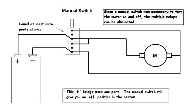
Control a toy car. The toy car is operated via a wired controller, rather than being radio-controlled. The intention is to utilize relays to control the toy through a parallel port. There are various types and models of relays,...
This is a single alarm circuit. The circuit includes automatic exit and entry delays, a timed bell cut-off, and a system reset. It has provisions for normally open and normally closed inputs. The single alarm circuit is designed to provide...
A clock-controlled relay, also known as a time delay relay, allows for the automatic activation of a load, such as a water pump, at a predetermined time. This device utilizes a standard clock mechanism to trigger the circuit, enabling...
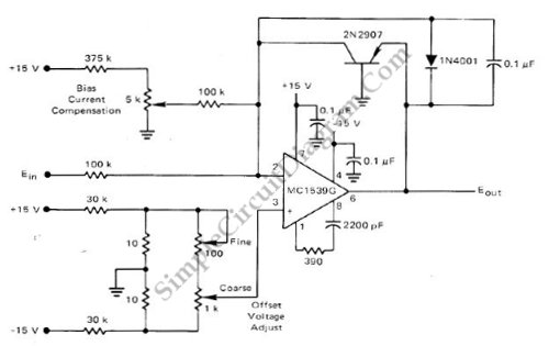
This low-cost logarithmic converter is constructed using an operational amplifier (op-amp) and a transistor. The circuit utilizes a Motorola MC1539G op-amp connected to a PNP transistor. The logarithmic converter circuit is designed to convert linear input signals into logarithmic output...
This page provides basic information about voltage comparator integrated circuits and is to act as reference material for other circuits. The circuits shown are based on the LM339 Quad Voltage Comparator chip or the LM393 Dual Voltage Comparator chip....