
Adjustable DC power supply circuit
The adjustable DC power supply circuit is designed to provide a stable output voltage that can be tailored to meet specific requirements. The circuit begins with a step-down transformer, which reduces the input AC voltage to a lower AC voltage suitable for rectification. The transformer is selected based on the desired output voltage and current specifications.
Following the transformer, a rectifier bridge composed of four diodes (VD1 to VD4) converts the AC voltage to pulsating DC. The rectifier bridge is configured in a full-wave arrangement, ensuring efficient conversion and minimizing ripple voltage. The output from the rectifier is then smoothed using a capacitor to reduce voltage fluctuations, providing a more stable DC voltage.
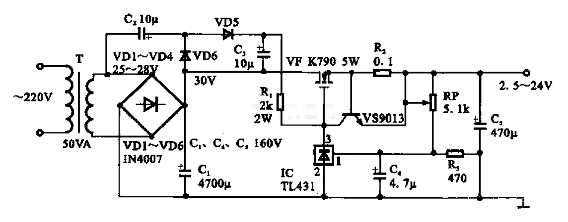
The heart of the circuit is the voltage regulator, which maintains the output voltage at the desired level despite variations in input voltage or load current. The adjustment potentiometer (RP, 5.1 kΩ) is connected to the voltage regulator, allowing users to fine-tune the output voltage within a range of 2.5 V to 24 V. This feature is particularly useful for applications requiring different voltage levels, such as powering various electronic devices or experimental setups.
For optimal performance, careful consideration should be given to the selection of components, including the transformer rating, diode specifications, and capacitor values. Additionally, heat dissipation must be addressed, particularly in the voltage regulator, to prevent thermal shutdown or damage.
Overall, this adjustable DC power supply circuit is a versatile solution for providing variable DC voltages, suitable for a wide range of electronic applications.Adjustable DC power supply circuit Shows an adjustable DC power supply circuit, which is composed of step-down transformer T, rectifier bridge pile (VD1 ~ VD4) and other parts of the voltage regulator circuit, the adjustment potentiometer RP (5.i kfl), the output voltage varies between 2.5-24 V.
Related Circuits
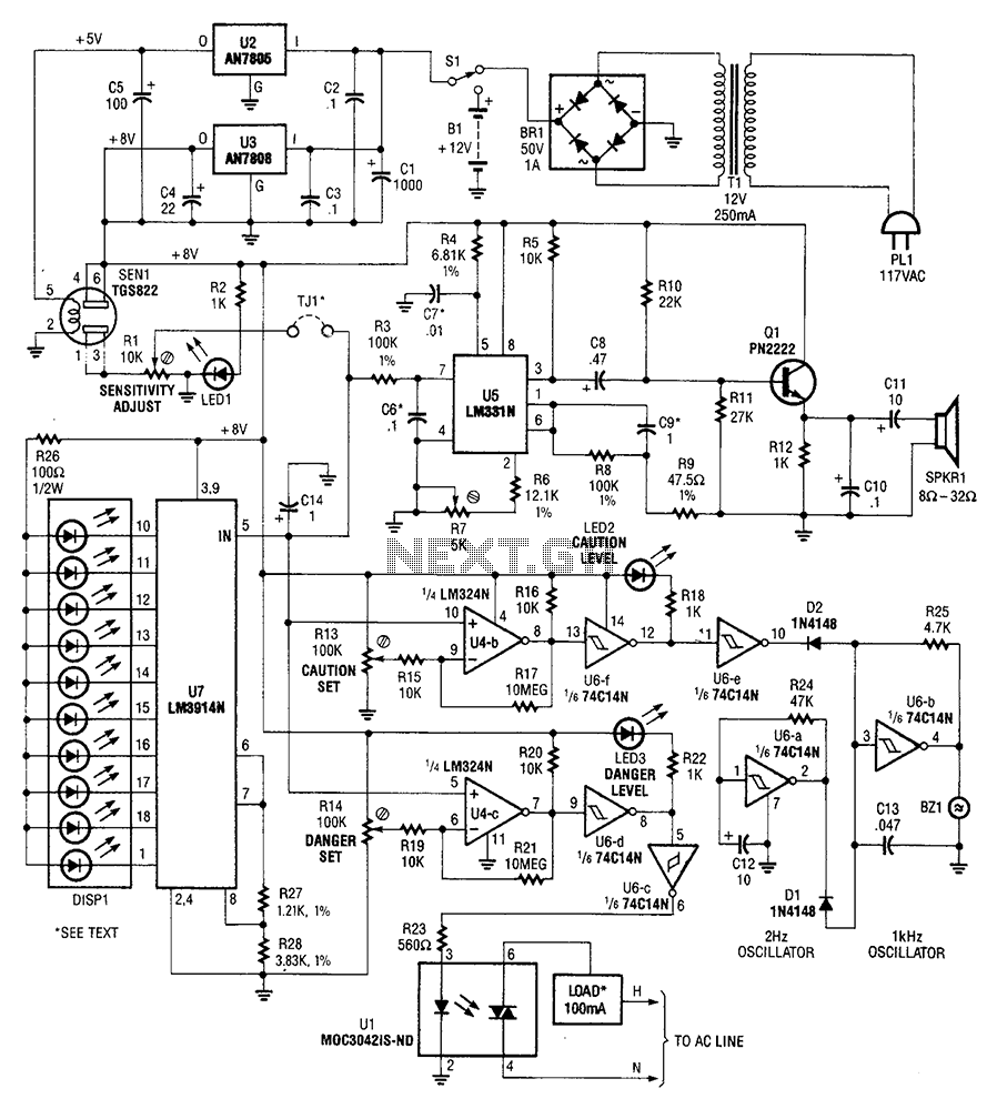
A gas sensor (from Allegro Electronics, Cornwall Bridge, CT06754 Ts GS823) activates in the presence of explosive gas. U5 functions as a voltage-to-frequency converter, with the sensor producing a frequency that is proportional to conductance. The output frequency varies...
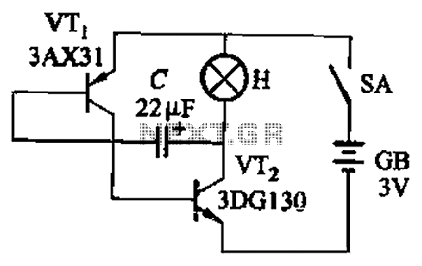
The circuit depicted in Figure 13-4 utilizes triode control. Two transistors, VTi and VTz, are coupled via a capacitor (C) to alternately turn on and off, producing a flashing light effect. The flash frequency is influenced by the capacitance...
The inexpensive flashlight utilized a small (0.22 Farad) capacitor for energy storage, which provided approximately 6.6 Joules of energy, significantly less than 1/1000th of the energy contained in a single AA alkaline cell. As a standard "super capacitor," it...
Here's PLL FM transmitter circuit from china. This circuit uses the familiar 2SC1971 for final power amplifier stage. The PLL controller of the FM transmitter use SAA1057 and PIC16F628 (download HEX file). More: If want to change the active...
The circuit operates at 380V for air flow. Power is supplied through a step-down transformer, which rectifies the output to 9V DC. When the pump operates correctly, a button labeled 'S' is activated. The circuit utilizes a TWH8778 component....
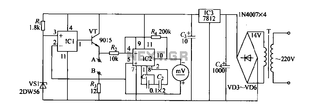
The contact resistance measuring circuit is illustrated in the figure. It primarily consists of a constant current circuit and an amplifying circuit. Operational amplifier IC1 is configured as a voltage follower, and the voltage across the load equates to...