
A sound and light control energy-saving switch circuit

The circuit design incorporates a step-down transformer to convert the high voltage (380V) to a lower voltage (9V DC), suitable for driving the control logic and associated components. The TWH8778 component plays a crucial role in ensuring safety and operational integrity by providing insurance protection against electrical faults. The photoelectric coupling device serves as an essential interface for detecting conditions that require the pump to operate or shut down, ensuring that the system responds accurately to environmental changes.
The use of a silicon triac allows for efficient control of the pump motor through the variable flood contactor, which is responsible for managing the power to the pump based on the signals received. The operational logic ensures that when the pump is active, the A and B connections are shorted, allowing for continuous operation. However, once the water level drops significantly, the system automatically disconnects these connections, triggering the F switch circuit in the TWH8778. This action cuts off the triac conduction, thereby stopping the pump motor to prevent damage due to dry running.
Safety features are built into the design, including the optical coupling device, which isolates the control circuit from the high voltage, minimizing the risk of electric shock. The resistance resistor further enhances safety by limiting current flow in case of a fault condition. This comprehensive approach ensures that the system is not only effective in its primary function of pumping water but also prioritizes user safety and equipment longevity.380V air flow I. Power through step-down transformer, rectifier output 9V DC oxime arrested. When the pump working fine basket lr. uT shake F 41Sf button S. * Circuit TWH8778 s unset is triggered - ~ .iHi, photoelectric coupling device to the bidirectional trigger IJr care mound i catch lll signal, bite Zhu silicon 3C: T i via conduction, variable flood contactor work. Its contact closed sets, connected to electric electromechanical {busy, pumping out water pumps. After pumping the pump nozzle from the water A. B ends shorted. TWH8778 insurance protection is turned on, then release the S. Pump still working properly. If the child after ten hours of continuous pumping after the ball well towel water is drained, A, B intoxicated end Anhydrous disconnected,} F switch circuit TWIf8778 is set.
And cut, triac also j ; conduction, contactor K release, pump motor will stop working. When installing, A, B two electric rice can be installed in place pump landscape mouth. Indiscriminately using optical coupling device in abundance to L security point of view, to prevent resistance resistor R. take a small electric shock accident.
Related Circuits
The schematic diagram of this robot is straightforward to comprehend. It is based on modifications made to a circuit from one of the reference books. The schematic for the robot features a basic structure that integrates various electronic components to...
The RF engineer often needs an instrument that can reliably and quickly check a low-frequency quartz crystal unit. However, such equipment is challenging to find, and engineers frequently refer to electronic circuit handbooks for schematics that can perform this...

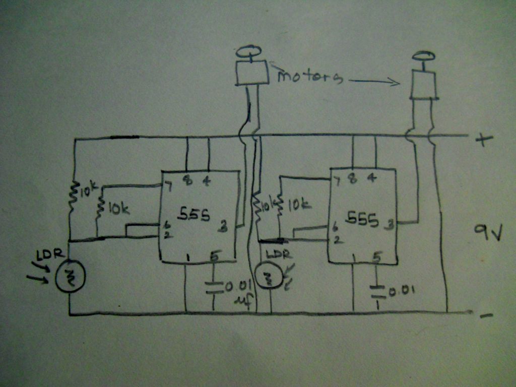
This is a simple water level alarm circuit made using a 555 timer IC. The circuit will produce an alarm when the water level reaches a preset level. The water level alarm circuit utilizing a 555 timer IC is designed...
The telephone repeater is a circuit designed to amplify the call signal, making it louder than the original. This circuit has been developed in response to specific requests. The telephone repeater circuit functions by receiving the incoming audio signal from...
A phase control circuit can be utilized to regulate the power supplied to an AC load. This circuit modulates the AC waveform by cutting portions of the cycle. A phase control circuit is an essential component in various applications where...
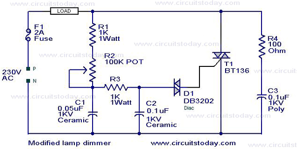
This is a modification of the Simple Lamp Dimmer/Fan Regulator circuit that was previously posted. The operation of the circuit remains the same as the original; however, it now includes a snubber circuit composed of resistor R4 and capacitor...