
DC-to-DC AC inverter
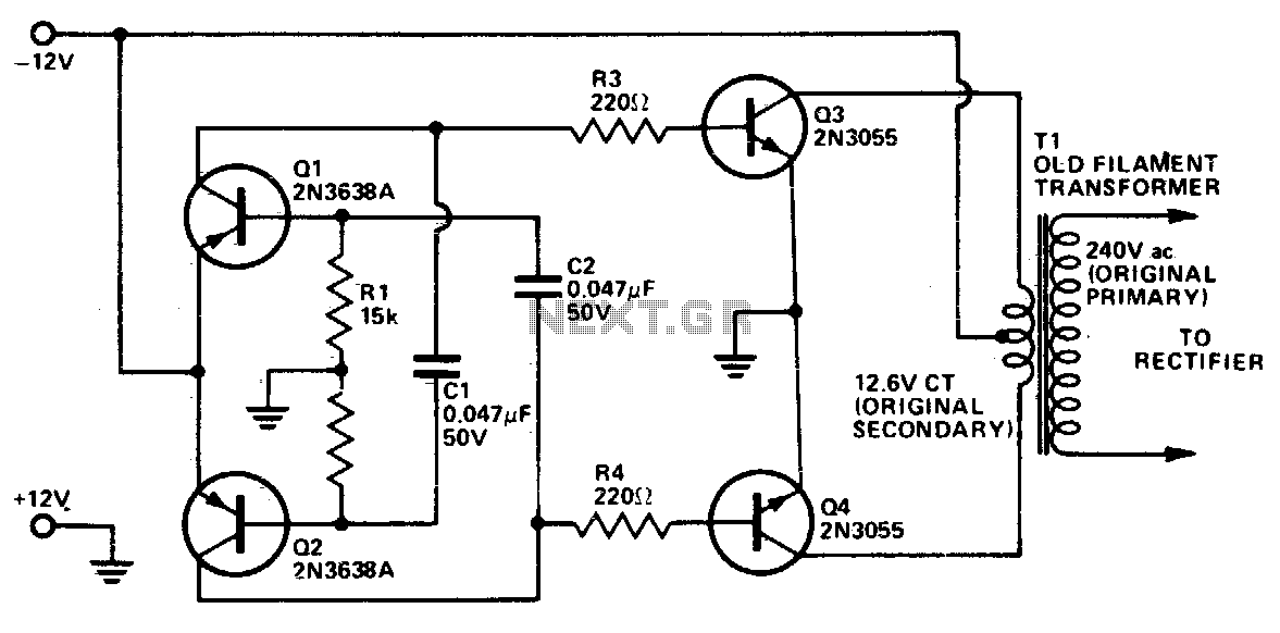
This inverter circuit operates as a cost-effective solution for converting DC power to AC power. The core of the design is an astable multivibrator, which generates a square wave signal at approximately 1200 Hz. This frequency is particularly advantageous, as it allows standard 50/60 Hz transformers to operate efficiently, thereby reducing energy loss during the conversion process.
The inverter employs two 2N3055 transistors, which are standard NPN power transistors capable of handling high currents. These transistors are configured in a push-pull arrangement, which effectively amplifies the square wave signal produced by the multivibrator. It is crucial for the transistors to be mounted on a heatsink to dissipate the heat generated during operation, preventing thermal overload and ensuring reliability.
In terms of components, capacitors C1 and C2 play a significant role in determining the oscillation frequency of the multivibrator. If the output frequency needs adjustment due to performance issues or load requirements, increasing the capacitance of these capacitors will lower the frequency, allowing for better compatibility with specific transformer designs.
The inverter's transformer must be selected based on the desired output power. It is essential to consider the conversion efficiency, which is estimated at around 60%. This means that the transformer should be rated higher than the expected output to accommodate losses and ensure stable operation. The rectifier filtering capacitors, which smooth the output waveform, are smaller in value due to the higher frequency of operation, thus enhancing the overall compactness and efficiency of the circuit.
Overall, this inverter design exemplifies a practical approach to power conversion, leveraging readily available components while maintaining a focus on cost-effectiveness and operational efficiency.This inverter uses no special components such as the torodial transformer used in many inverters. Cost is kept low with the use of cheap, readily available components. Essentially, it is a power amplifier driven by an asta-ble multivibrator. The frequency is around 1200 Hz which most 50/60 Hz power transformers handle well without too much loss. Increasing the value of capacitors Cl and C2 will lower the frequency if any trouble is experienced However, rectifier filtering capacitors required are considerably smaller at the higher operating frequency. The two 2N3055 transistor should be mounted on an adequately sized heatsink. The transformer should be rated ac-cordingto the amount of output power required allowing for conversion efficiency of approximately 60%.
🔗 External reference
Related Circuits
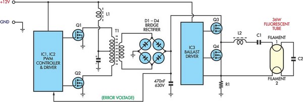
Fluorescent tubes consume significantly less energy compared to incandescent lamps and have a much longer lifespan. Additional benefits include diffuse, glare-free lighting and reduced heat output. Due to these advantages, fluorescent lighting is commonly preferred in commercial and retail...
This converter features a central component, the CMOS 4047, which converts a 12V DC voltage into a 220V AC voltage. The 4047 operates as an astable multivibrator. At pins 10 and 11, a symmetrical rectangular signal is generated, which...
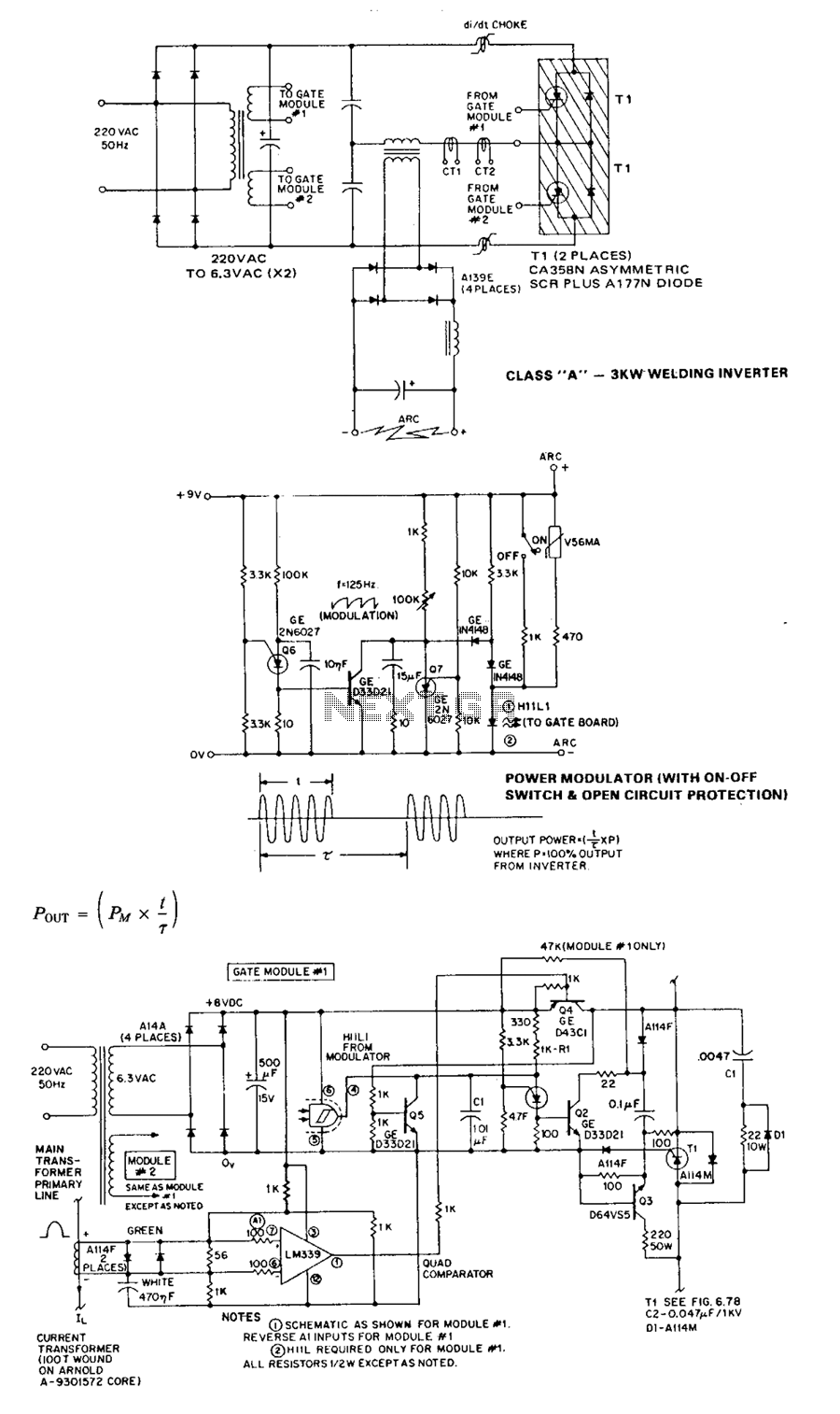
The Class A series resonant inverter is recognized for its high efficiency, low cost, and compact size, provided the operating frequency exceeds approximately 3 kHz. However, it faces challenges, particularly in high power versions, regarding the difficulty of achieving...
This project report discusses a DC/AC pure sine wave inverter. It focuses on DC to AC electrical power inverters, which are designed to efficiently convert a DC power source into a high voltage AC supply, similar to standard electrical...
Using this circuit you can convert the 12V dc into the 220V Ac. In this circuit, 4047 is used to generate the square wave of 50Hz and amplify the current and then amplify the voltage by using the step...
An Inverter is a device that converts 12 volts d.c to 120 volts a.c., which is what we use in our homes. This project will handle about 300 watts, which is perfect for lights, small T.V.s and radio equipment....