
Project report of DC/AC pure sine wave inverter

The DC/AC pure sine wave inverter is an essential device in various applications, including renewable energy systems, uninterruptible power supplies (UPS), and portable power systems. This inverter type generates a smooth and continuous sine wave output, which is critical for the proper operation of sensitive electronic devices and appliances that require a stable AC voltage.
The inverter operates by first converting the direct current (DC) from a battery or solar panel into alternating current (AC). This process typically involves several stages, including DC-DC conversion, where the input voltage is adjusted to a suitable level, and then an inverter stage that utilizes switching devices such as MOSFETs or IGBTs to create the AC waveform. The output is then filtered to ensure that the waveform closely resembles a pure sine wave, minimizing harmonic distortion and providing a clean power supply.
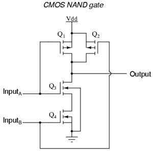
Key components of the inverter circuit include a microcontroller for control and monitoring, an oscillator circuit for generating the required frequency, and a transformer for voltage stepping. Additional protection circuits may be implemented to safeguard against overvoltage, overcurrent, and thermal overload conditions.
The efficiency of a pure sine wave inverter is a significant factor in its design, as it directly affects the performance and reliability of the entire system. Factors such as switching frequency, component selection, and thermal management play crucial roles in optimizing the inverter's efficiency.
In summary, the DC/AC pure sine wave inverter is a sophisticated electronic device that transforms DC power into high-quality AC power, making it suitable for a wide range of applications, particularly where clean power is essential for the operation of sensitive electronic equipment.Here the project report of DC/AC pure sine wave inverter. This report focuses on DC to AC electrical power inverters, which aim to efficiently transform a DC power source to a high voltage AC supply, just like electrical power that would be.. 🔗 External reference
Related Circuits
The double-ended working core square wave inverter transformer area product formula Bm represents the maximum magnetic flux. The primary side of the transformer features switches S1 and S2 in parallel with IRF32055. This parallel configuration is primarily due to...
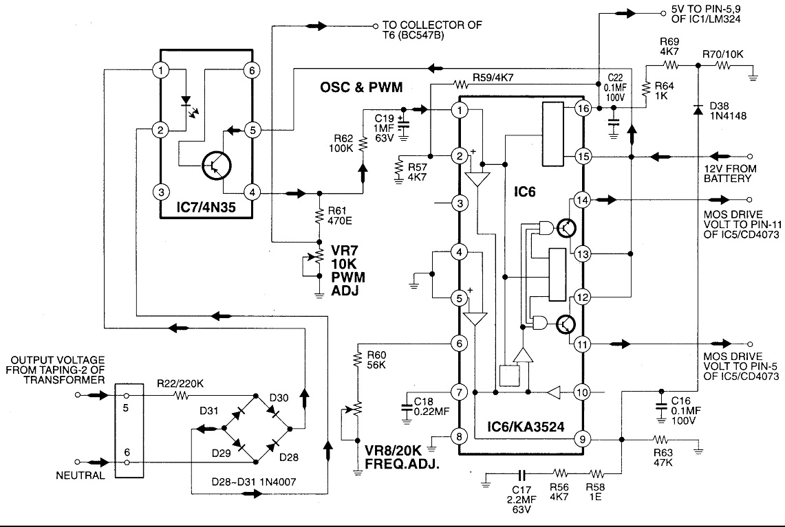
Circuit No. 1 (Oscillator Circuit and Feedback Circuit) Circuit No. 2 (MOS Driver Circuit) Final Product: - Operation of Circuit No. 1 (Oscillator Circuit and Feedback Circuit) This inverter utilizes Pulse Width Modulation (PWM) technology. The working principle of...
An ultrasonic sound wave can be generated using an electronic circuit. This simple electronic circuit can generate an ultrasonic wave with a frequency range of 12 kHz and above. The electronic circuit designed for generating ultrasonic sound waves typically utilizes...
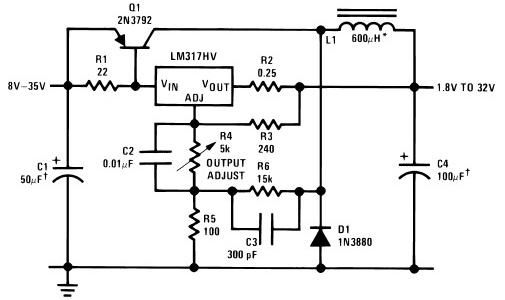
The circuit diagram of this LM317 power supply electronic project requires a few external components. The input voltage for this project must be between 8 and 35 volts, providing a variable output voltage ranging from 1.8 volts to 32...
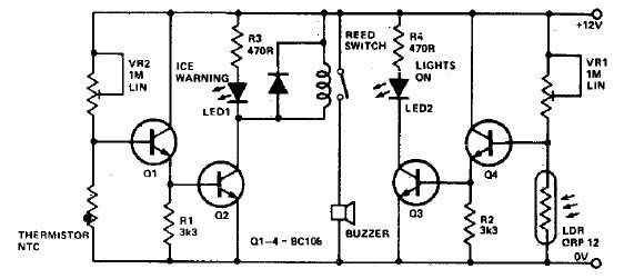
This electronic project circuit diagram for an ice warning and lights reminder system alerts drivers when their vehicle lights should be activated and warns them if the outside temperature approaches zero degrees Celsius. The system employs an LED indicator...
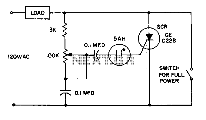
The 5AH will trigger when the voltage across the two 0 µF capacitors reaches the breakdown voltage of the lamp. Control can be obtained from full off to 95% of the half-wave RMS output voltage. Full power can be...