
LM723 voltage regulator circuit diagram consisting of cars

The circuit design incorporates the LM723 voltage regulator, which is a versatile and reliable component widely used in power supply applications. In this configuration, the LM723 is employed as a switching regulator to optimize the charging process of the lead-acid battery. This method improves efficiency by minimizing energy losses typically associated with linear regulation.
The primary function of the LM723 is to regulate the output voltage to a stable level, ensuring that the battery receives the appropriate voltage for charging without exceeding the safe limits. The standard charging voltage for a 12V lead-acid battery is typically around 13.8V, and the circuit is designed to maintain this voltage under varying load conditions. This is achieved through feedback mechanisms that monitor the output voltage and adjust the excitation current supplied to the generator accordingly.
Resistor R2 plays a critical role in this circuit by setting the desired output voltage level. Its value is chosen to ensure that the voltage remains stable and does not fall below or exceed the specified threshold, which is crucial for battery health and longevity.
The use of the 2N2063A transistor as Q1 allows for efficient control of the current flowing to the generator's excitation coil. As a PNP transistor, it is well-suited for high-side switching applications, providing a robust means of controlling the power delivered to the generator. Rated at 10A, it can handle the necessary current levels without overheating or failing, ensuring reliable operation.
Overall, this circuit represents an advanced approach to automotive battery management, replacing traditional systems with a more efficient and reliable solution that extends battery life and enhances performance. Cars are fixed as shown in the circuit composed of LM723 regulator circuit, it can replace the use of an automobile generator system consisting of electromechanical charging re gulator, performance is better than the latter. It makes 12V lead - acid battery will not charge less than or overcharge, thus extending battery life. Circuit LM723 used as a switching regulator for controlling the generator excitation current. R2 resistance is conditioned so that the charging voltage can be maintained at a standard car battery voltage over 13.8V.
Q1 is 2N2063A (SK3009), 10A, PNP transistors.
Related Circuits
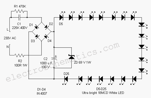
This white LED light illuminates the porch with cool white light. The circuit features a simple and energy-saving design. Its current consumption is practical. The white LED light circuit is designed to provide efficient illumination while minimizing energy usage. The...
The following circuit illustrates a Solar Tracker Circuit Diagram. This circuit is based on the LM339 integrated circuit. Features include a 10nF ceramic capacitor (103z) and a 1MΩ resistor. The Solar Tracker Circuit utilizes the LM339 quad comparator IC to...
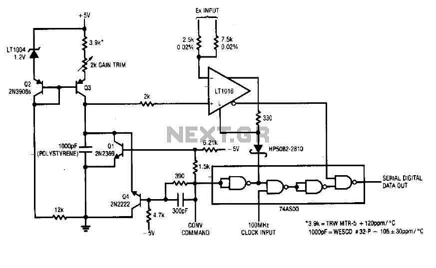
Each time a pulse is applied to the control input for conversion, Q1 resets the 1000 pF capacitor to 0 V. This resetting action takes 200 ns, after which the capacitor begins to charge linearly. In precisely 10 microseconds,...
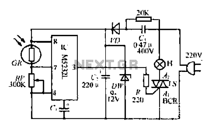
The DW L11 capacitor steps down voltage into the Jenru half crossing according to Yin electrical specifications. After receiving power at the bin CI SH output terminal, it regulates the voltage to liVI/r j, ensuring a right cut in...
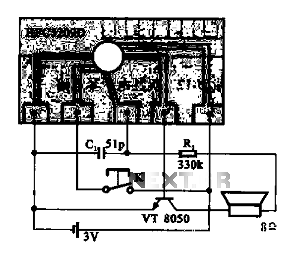
A simple phone automatically displays the recording circuit. In this circuit, after the call, the Ming sound start switch K is activated by the sound of the automatic message HFC5209D. The described circuit functions as an automatic call recording system...
A DC capacitor tester circuit diagram utilizing a 555 timer is presented. The tester includes a pulse generator, a one-shot circuit, a DC amplifier, and a meter indication circuit. It is capable of measuring capacitors ranging from nanofarads (nF)...