
DC capacitor tester circuit diagram composed of 555

The DC capacitor tester circuit employs a 555 timer IC in astable mode to generate a square wave pulse. The frequency of this pulse is inversely related to the capacitance of the capacitor being tested. The capacitor under test is connected in parallel with a resistor, forming an RC time constant that determines the charging and discharging rate of the capacitor.
When the capacitor charges through the resistor, the voltage across the capacitor reaches a threshold that triggers the 555 timer to switch states, resulting in a pulse output. This pulse is then processed by a one-shot circuit, which generates a single output pulse of a fixed duration each time the input pulse is detected. This pulse width is directly proportional to the capacitance value.
The DC amplifier is used to amplify the output signal from the one-shot circuit to a level suitable for driving a meter indication circuit, which displays the measured capacitance. The meter can be an analog or digital type, depending on the design requirements. The segmented ranges allow the tester to provide accurate measurements across a wide spectrum of capacitor values, making it a versatile tool for electronic testing and troubleshooting.
This circuit is particularly useful in the field of electronics for evaluating capacitor health and performance, ensuring that components meet specified tolerances before being incorporated into larger circuits. Proper calibration and component selection are essential for achieving precise measurements and reliable operation of the capacitor tester.DC capacitor tester circuit diagram composed of 555 is shown as the chart. The tester is composed of the pulse generator, one-shot, DC amplifier and meter indication circuit. It can measures the npF ~ 10?F capacitor. The range is divided into 0 ~ 100PF, 0 ~ 1nF, 0 ~ 10nF, 0 ~ 100nF, 0 ~ 1?F, 0 ~ 10?F.. 🔗 External reference
Related Circuits
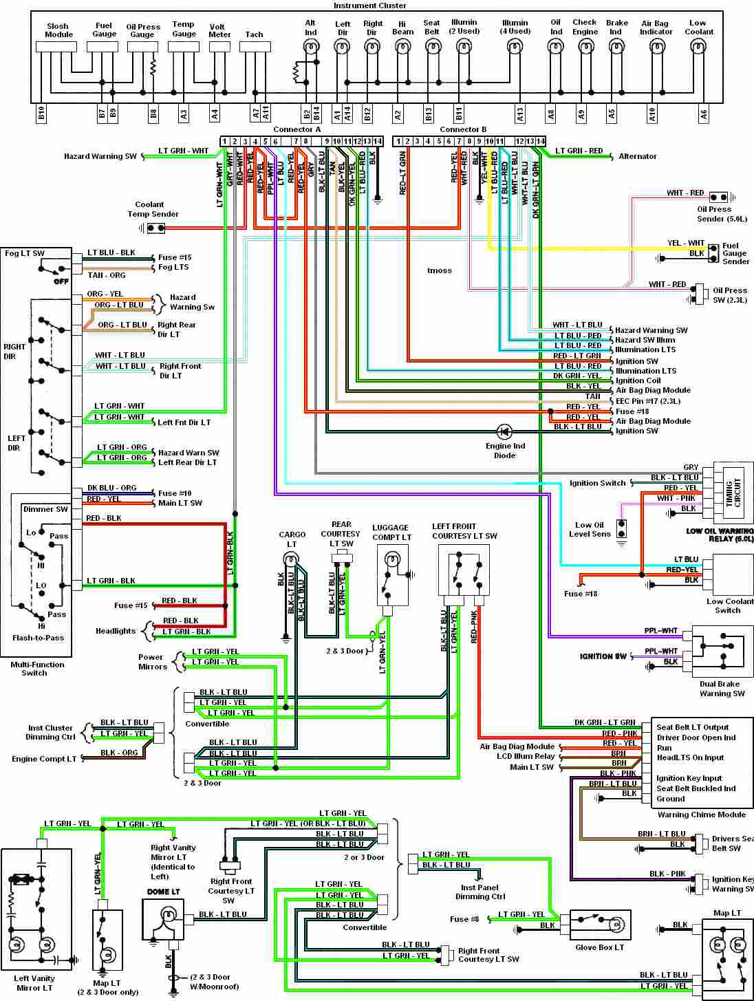
Automotive diagram for the instrument cluster of the 1987-1993 Ford Mustang (Third Generation). The instrument cluster for the 1987-1993 Ford Mustang serves as a critical interface for the driver, providing essential information about the vehicle's operational status. This cluster typically...

This stereo amplifier utilizes the NE5517/A and features an excellent tracking accuracy of 0.3 dB, which is typical. The offset can be adjusted using the potentiometer, Rp. For AC-coupled amplifiers, the potentiometer can be substituted with two 5.1 k...
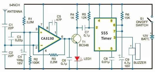
Cellular phone detector circuit schematic using common electronic parts The cellular phone detector circuit is designed to identify the presence of a cellular phone within a specified range. This circuit utilizes basic electronic components, making it accessible for hobbyists and...
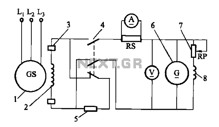
Adjust the exciter field rheostat RP to change the exciter output voltage, which in turn adjusts the generator excitation current, allowing for modifications to the generator output voltage for various purposes. The exciter field rheostat (RP) is a critical...
This article discusses a fully automatic 6V 4.5AH battery charger circuit that utilizes the LM317T integrated circuit along with a few additional components. The circuit is designed to charge a 6V lead-acid battery. The circuit utilizes the LM317T voltage regulator,...

This second-order low-pass filter utilizes a 741 operational amplifier and can be tuned from 2.5 kHz to 25 kHz. The circuit is beneficial in audio and tone control applications. R1 and R2 are ganged potentiometers. The described circuit features a...