
Power Supply Current and Voltage Regulated By LM317 or LM350

This circuit design utilizes a rotary switch to effectively manage current range selection, which is essential in applications requiring precise current control. The rotary switch offers a reliable method to toggle between different resistance settings, optimizing the circuit's performance across various operational conditions.
For the lower current ranges, incorporating a potentiometer allows for fine-tuning of the current output, enhancing the versatility of the circuit. The inclusion of a small series resistor with the potentiometer ensures that the circuit remains stable and prevents excessive current flow that could lead to damage.
In higher current applications, fixed resistors are preferred as they provide consistent and reliable performance without the variability introduced by a potentiometer. The recommendation to construct two circuits allows for dual polarity operation, which is beneficial in many electronic applications where both positive and negative voltages are required.
Connecting the circuits in parallel can increase the total current capacity, while a series configuration can elevate the output voltage, enabling the design to adapt to a wide range of power requirements.
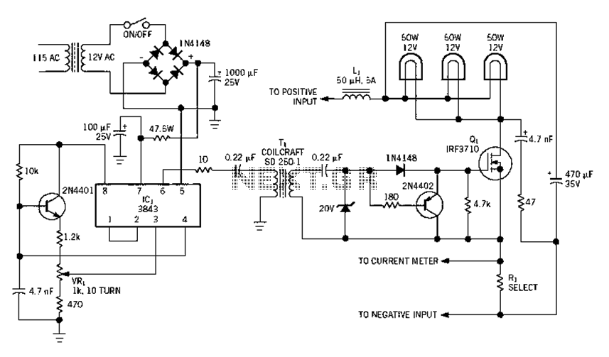
The selection of the transformer is critical, as it determines the input voltage and current available to the circuit. The choice of voltage regulator, such as the LM317 or LM350, further influences the maximum output current. The LM317 is suitable for applications requiring up to 1.5 amps, while the LM350 can handle up to approximately 3 amps, allowing for flexibility depending on the specific needs of the application.
Overall, this circuit provides a robust solution for applications requiring adjustable current ranges, with considerations for safety, stability, and adaptability to various electrical demands.In this circuit I have used a Rotary Switch to select Various Current ranges as a Potentiometer is not very practical for the lower resistance/High Current Ranges. But if you wish to change it to a pot, you can try it. * It is practical to use a pot on the lower current ranges so the lowest switch range could be a pot with a small series resistor.
Allowing for adjustment from say 10 mA to 500 mA . Than use fixed resistors on the higher current ranges. I recommend in making two of these. This will allow for Plus and Minus supply voltages, when needed. They can Also be Paralleled or placed in Series for Higher Currents or Higher Voltages, As is Sometimes Needed. Output Voltage and current depends somewhat on the transformer used, as well as which Regulator used.
You have a choice of an LM317 for 1. 5 amps Max, or an LM350 to give about 3 amps Max. 🔗 External reference
Related Circuits
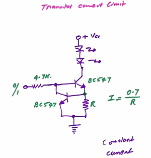
This is a constant current source LED driver. When the upper NPN transistor is activated by a voltage through a 4.7kΩ resistor, the LED lights up. It is assumed that the lower NPN transistor is absent. The current flowing...
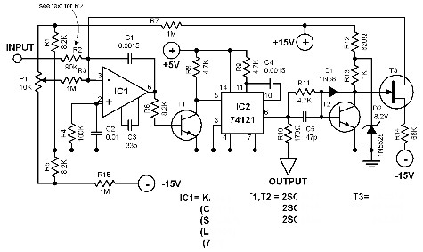
This voltage-to-frequency converter is designed to connect to a frequency counter to display the measured voltage value. This converter-counter combination creates an inexpensive yet functionally complete digital voltmeter. The circuit outputs TTL-compatible pulses that are 5 µs wide. The...
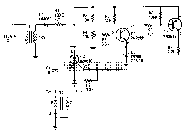
A step-down transformer T1 reduces the incoming line voltage to approximately 48 Vac, which is then rectified by diode D1. The resulting direct current charges capacitor C1 through a current-limiting resistor R1 to a voltage level set by R4....
Electrical equipment provided for a power supply circuit design in the power section, as illustrated below. The power supply circuit design is a critical component in various electronic systems, serving as the backbone for powering other devices. The schematic typically...
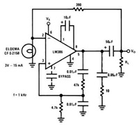
This device has a quiescent power drain of 24 milliwatts when operating from a 6 V supply, making the LM386 ideal for battery operation. According to the application hints section of the LM386 datasheet, two pins (1 and 8)...
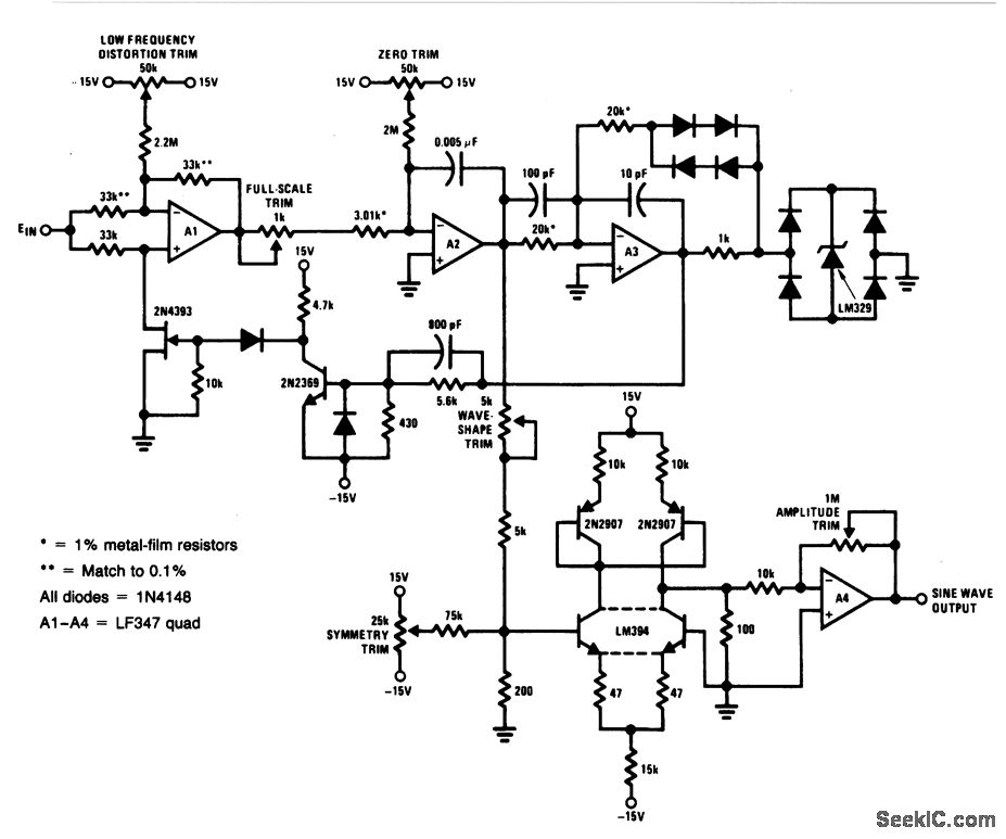
For a 0- to 10-V input, this circuit generates sine-wave outputs ranging from 1 Hz to 20 kHz, achieving linearity better than 0.2%. The distortion level is approximately 0.4%, and both the frequency and amplitude of the sine-wave output...