
220V 12V 150W switching power supply circuit diagram

The power supply circuit design is a critical component in various electronic systems, serving as the backbone for powering other devices. The schematic typically includes a transformer, rectifier, filter, and voltage regulation stages, ensuring that the output voltage is stable and suitable for the intended application.
1. **Transformer**: The circuit begins with a transformer that steps down the voltage from the mains supply to a lower AC voltage. The transformer is selected based on the required output voltage and current specifications. It is essential to ensure that the transformer has sufficient power rating to handle the load without overheating.
2. **Rectifier**: Following the transformer, a rectifier converts the AC voltage into DC voltage. This can be achieved using either a half-wave or full-wave rectifier configuration. A full-wave bridge rectifier is commonly used for its efficiency and ability to provide a smoother DC output. The rectifier diodes must be rated for the peak inverse voltage (PIV) and forward current to prevent failure during operation.
3. **Filter**: The rectified DC voltage is often pulsating and requires smoothing. This is accomplished using filter capacitors, which store charge and release it to reduce voltage ripple. The choice of capacitance value is crucial; larger capacitors provide better smoothing but may increase inrush current during startup.
4. **Voltage Regulation**: To maintain a consistent output voltage despite variations in input voltage or load conditions, a voltage regulator is employed. This can be a linear regulator for low power applications or a switching regulator for higher efficiency in more demanding applications. The regulator ensures that the output remains within specified limits, protecting downstream components.
5. **Protection Features**: Additional components such as fuses, circuit breakers, and transient voltage suppressors may be included to enhance the reliability and safety of the power supply circuit. These components help prevent damage from overloads, short circuits, and voltage spikes.
In summary, the design of a power supply circuit involves careful selection and integration of various components to ensure efficient and reliable operation. Each stage of the circuit plays a vital role in transforming and regulating electrical energy for use in electronic devices.Electrical equipment supplied to a power supply circuit design power section, as shown below:
Related Circuits
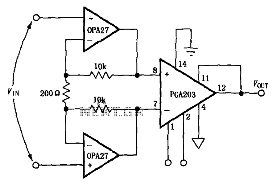
The circuit depicted in the figure features a PGA203 operational amplifier (op amp) and two OPA27 op amps, forming a low-noise differential amplifier. The input stage utilizes the PGA203 in conjunction with the two OPA27 op amps. The non-inverting...
A schematic arrangement for a two-quadrant controller is shown in the figure below. This figure illustrates the outer speed control loop and the inner current control loop. The tachogenerator derives the speed feedback signal; alternatively, an approximation of the...

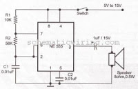
This circuit generates a siren sound when switch S1 is pressed. The sound frequency increases as capacitor C1 charges, and when switch S1 is released, the frequency decreases as capacitor C1 discharges. The circuit operates on a simple principle of...
Schematic diagram. A presentation of the element-by-element relationship of all parts of a system. A schematic diagram serves as a crucial tool in electronic design and engineering, representing the interconnections and relationships between various components within a system. It provides...
This circuit generates an oscillating frequency of approximately 1 kHz, which can be adjusted by changing the value of resistor R1. The speaker will emit a continuous beep sound at this frequency. The circuit utilizes a basic oscillator configuration,...
This power supply was designed for use with the Simple hybrid amplifier published elsewhere in this issue. It is suitable for various applications. A cascade generator is employed for the 170 V output, a switch mode supply for the...