
Voltage controlled sine wave oscillator

This circuit is designed to generate a precise sine-wave output based on a specified input voltage range of 0 to 10 V. The operational frequency range spans from 1 Hz to 20 kHz, making it suitable for various applications requiring accurate waveform generation. The circuit maintains linearity better than 0.2%, which is critical for applications where signal fidelity is paramount. The distortion level of approximately 0.4% indicates that the output waveform closely resembles an ideal sine wave, which is essential for audio and signal processing tasks.
The calibration procedure is integral to ensuring the circuit operates correctly. The first step involves applying a 10 V input, which serves as a reference point for the subsequent adjustments. The wave-shape trim and symmetry trim controls allow for fine-tuning of the output waveform to achieve minimal distortion. A distortion analyzer is employed to provide quantitative feedback during this calibration phase, ensuring that adjustments yield the desired results.
Following the initial calibration, the circuit is tested at a lower frequency of 10 Hz. This step is crucial for ensuring the circuit's performance at lower frequencies, which can often be more challenging due to increased distortion effects. The low-frequency distortion trim is adjusted to minimize any distortion detected at this frequency.
Finally, the zero and full-scale potentiometers are adjusted to establish a direct correlation between input voltage levels and output frequency. This ensures that a 500 V input results in a 1 Hz output, while a 10 V input produces a 20 kHz output. Such a calibration process not only verifies the circuit's accuracy but also enhances its reliability across the specified input range and frequency spectrum. The design and calibration of this circuit make it a versatile tool for signal generation in various electronic applications.For a 0- to 10-V input, this circuit produces sine-wave outputs of 1 Hz to 20 kHz, with better than 0. 2% linearity. Distortion is about 0. 4% and the sine-wave output frequency and amplitude settle instantaneously to a step-input change. To calibrate, apply 10 V to the input and adjust the wave-shape trim and symmetry trim for minimum distortion on
a distortion analyzer. Next, adjust the input voltage for an output frequency of 10 Hz and trim the low-frequency distortion for minimum indication on the distortion analyzer. Finally, alternately adjust the zero and full-scale pots so that inputs of 500 V and 10 V yield respective outputs of 1 Hz and 20 kHz.
🔗 External reference
Related Circuits
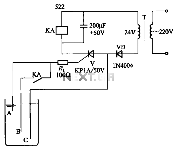
The circuit depicted in Figure 11-14 utilizes a unidirectional thyristor within liquid level automatic control systems. It incorporates electrodes that serve as sensing elements for detecting the level of water or other conductive liquids. The circuit features a current...

This design schematic illustrates a Crystal Colpitts oscillator that can be implemented using a transistor and a parallel mode crystal. In this circuit, the crystal functions as an inductance. A large value capacitive divider is utilized between the gate,...
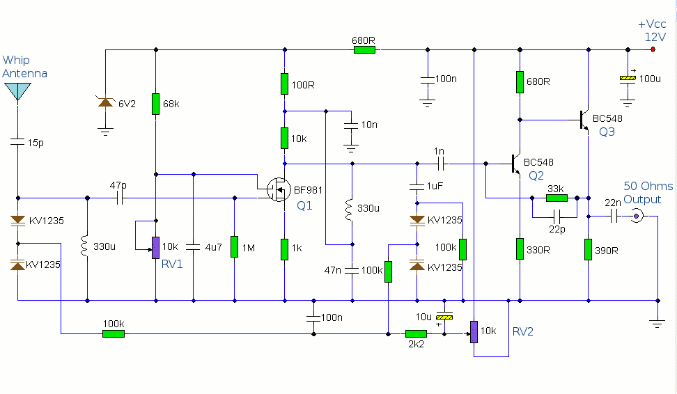
This circuit is designed to amplify the input from a telescopic whip antenna. The preamplifier is designed to cover the medium waveband from about 550KHz to 1650KHz. The tuning voltage is supplied via RV2, a 10k potentiometer connected to...
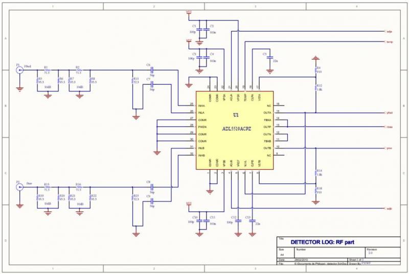
The ADL5519 is particularly focused on bandwidth, specified up to 8 GHz, though it remains usable at 10 GHz with reduced dynamic range. It features two channels, allowing for the measurement of power transmitted to the antenna and the...
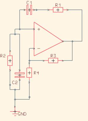
One of the simplest sine wave oscillators is the Wien Bridge Oscillator. Any circuit requires two conditions to oscillate. Tracing the path from the input, through the feedback network, and back to the input, there must be an overall...
This is a power supply circuit that produces a voltage range of 12 to 24 V. It is straightforward, requiring only a bridge rectifier, a filter capacitor, and a transformer, without the need for a regulator. A bridge rectifier...