
Power Supply For Amplifier

The power supply circuit for an amplifier is a crucial component that ensures the amplifier operates effectively. It typically consists of a transformer, rectifier, filter, and voltage regulator.
The transformer steps down the AC voltage from the mains supply to a lower AC voltage suitable for the amplifier. This is followed by a rectifier, which converts the AC voltage to pulsating DC. Commonly used rectifiers include full-wave or bridge rectifiers, which provide a smoother DC output.
Next, the filter stage, often composed of capacitors, smooths the pulsating DC to reduce ripple voltage. This filtering is essential for maintaining a stable voltage supply to the amplifier, as excessive ripple can lead to distortion in the amplified signal.
Finally, a voltage regulator may be employed to ensure that the output voltage remains constant despite variations in load or input voltage. Linear regulators or switching regulators can be used, depending on the requirements for efficiency and heat dissipation.
Overall, the design of the power supply for an amplifier circuit must consider factors such as voltage levels, current requirements, and the overall efficiency of the circuit to ensure optimal performance of the amplifier. Proper layout and component selection are also critical to minimize noise and interference in the audio signal.The following circuit shows about Power Supply For Amplifier Circuit Diagram. Features: Easy to build, supported by an adeguate electric response, make a .. 🔗 External reference
Related Circuits
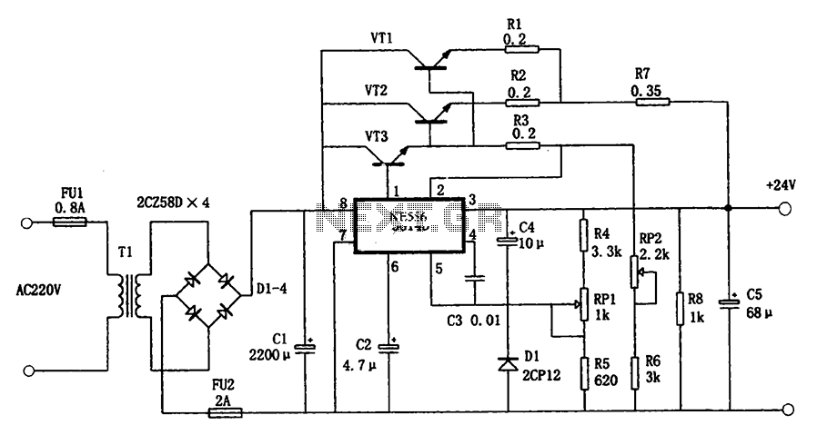
The circuit illustrated in the figure is a +24V, 1.9A power supply design. It employs the 5G14D domestic integrated voltage regulator as the core component, supported by three external power transistors. While the 5G14D voltage regulator has a rated...
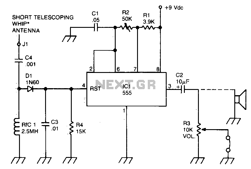
A sidetone oscillator is a specific type of audio astable multivibrator. Keying is achieved by turning the oscillator on and off through the application of a positive DC potential, which is generated from the RF signal to the reset...
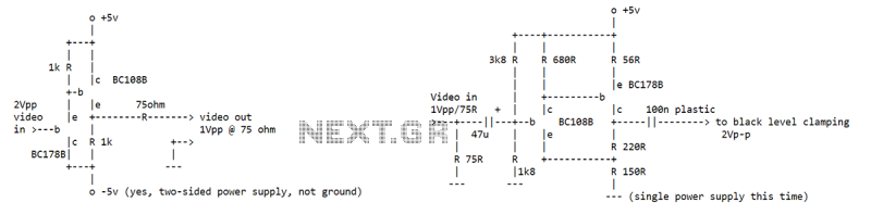
I've seen an NE592 used as a video buffer amp at the end of a 75 ohm line. Used so that the 75 ohm line could drive all kinds of neat processing stuff without affecting the signal (that's what...
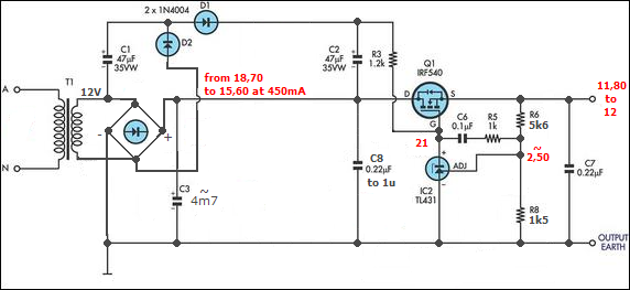
The half-linear design allows for reduced thermal considerations, as the linear regulator only needs to handle 1-5W instead of the full 75W per rail. MOSFETs operate in their linear region, just below the rated voltage for RDS(on), but they...
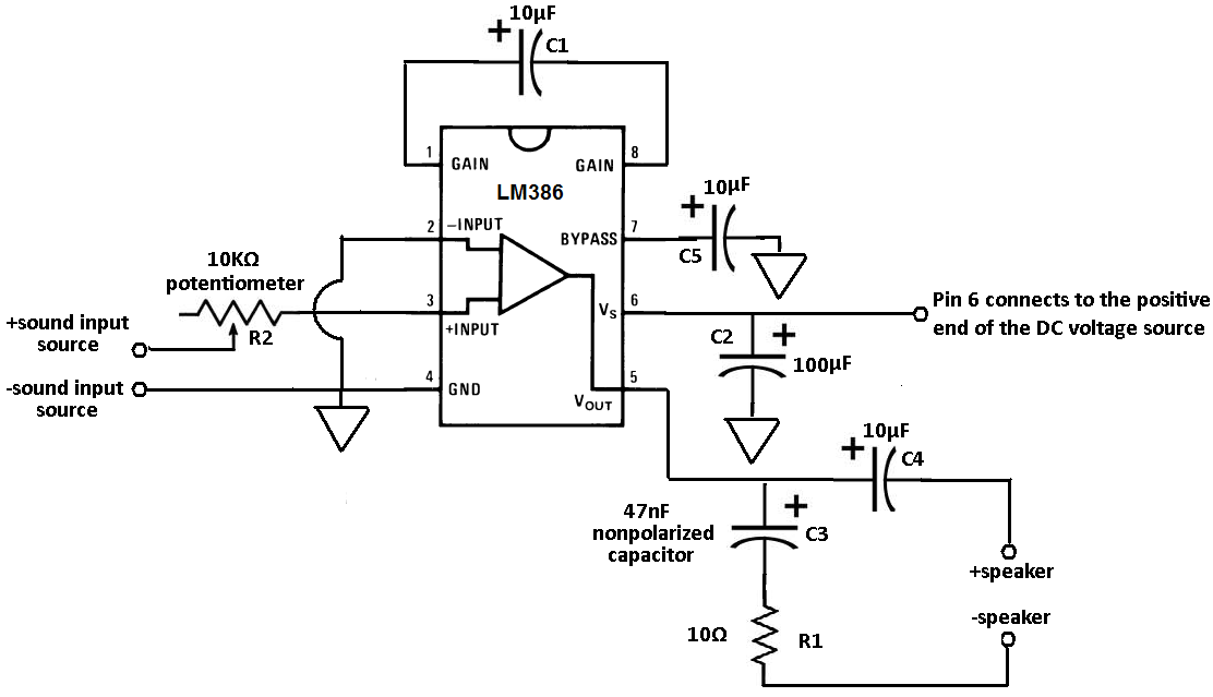
Terminals 1 and 8 serve as the gain control for the amplifier. Adjustments to the gain can be made by connecting a resistor and capacitor, or just a capacitor, between these terminals. In this circuit, a 10 µF capacitor...

This project involved the design of an audio amplifier that delivers substantial output power while maintaining a minimal parts count and high quality. The power amplifier section utilizes only three transistors along with a few resistors and capacitors arranged...