
Video amplifier

The NE592, now also known as the LM592, serves as a highly effective video buffer amplifier, particularly suited for applications involving 75-ohm transmission lines. This device is essential in maintaining signal integrity while interfacing with various processing equipment. The NE592 and LM592 are interchangeable, sourced from multiple manufacturers including Texas Instruments, Harris, Philips (Signetics), and Motorola. It is important to note that these amplifiers come in both 8-pin and 14-pin configurations; the latter includes two additional gain control pins, enhancing flexibility in design.
Unlike traditional operational amplifiers, the NE592 does not utilize feedback mechanisms for gain control, which necessitates careful design considerations regarding signal amplification. The circuit is optimized for speed, requiring the implementation of a ground plane and the placement of ceramic bypass capacitors in close proximity to the supply pins to mitigate noise and ensure stability.
In video applications, the DC components are typically managed through AC coupling, particularly at input stages. This design choice underscores the necessity of black level clamping when processing video signals. The video signal's voltage levels are referenced to a floating black level, which can vary. A standard video input configuration employs a 75-ohm terminating resistor connected to ground, with a coupling capacitor, typically around 50μF, feeding the input buffer.
The output stage of the circuit is designed to be straightforward yet effective. A serial matching resistor is incorporated to ensure that a 2Vp-p video signal is fed into the buffer, yielding the standard 1Vp-p output for downstream equipment. A simple black level clamp can be constructed using a 1N4148 signal diode, reverse-biased to ground from the output of the input buffer, in parallel with a 4.7kΩ resistor. This configuration ensures that the sync tips align at (ground - diode threshold voltage), effectively adjusting the black level for a 2x amplified video signal.
To achieve optimal performance, it is critical to implement robust power supply bypassing. This includes the use of at least 220μF electrolytic capacitors and 100nF ceramic capacitors positioned near the transistors in both the input and output stages. Such careful attention to component selection and layout will enhance the overall signal quality, ensuring reliable operation even if it may not meet broadcast standards. I've seen an NE592 used as a video buffer amp at the end of a 75 ohm line. Used so that the 75 ohm line could drive all kinds of neat processing stuff without affecting the signal (that's what a buffer is after all, right?) Now National Semiconductor makes an LM592 that's also a video amp. They are the same chip. Sources for NE/SE/LM/uA592 include TI, Harris, Philips (Signetics) and Motorola. Be aware that there are 8 and 14 pin versions of it, the difference being that the larger package has two additional gain control pins.
It's not really an op-amp, so you can't use feedback to control the gain. Additionally, they're _fast_ circuits, so use a ground plane and ceramic bypassing caps as close as possible to the supply pins.
The DC components in video are normally a non-issue. Most video equipment are AC coupled (at least the input), which is the reason why you can't get away without black level clamping if you plan to process the video signal. Nothing is said about the actual voltage levels of the video signal, they are just referenced to the black level which may float anywhere (well if I remember right, you're guaranteed to have less than 1W power dissipation in the terminating resistor with standard video...).
A typical video input has a 75 ohm terminating resistor to ground and then the signal is fed to the input buffer via a ~50uF electrolytic cap. Anyway, here's a simple discrete video output stage. Can't get much simpler than this. Note that there's a serial matching resistor on the output, so you'll have to feed 2Vp-p video into the buffer to get the usual 1Vp-p into the equipment you're driving.
This is the way it's usually done. Sorry for the crude transistors, but I hate doing ASCII graphics. The simplest black level clamp consists of a signal diode (1N4148) reverse-biased to ground from the output line of the input buffer above and a 4k7 resistor in parallel with it. That forces the sync tips to be at (gnd - threshold voltage of the diode), which shifts the black level of a 2x amplified video reasonably close to ground.
Add that and you can connect the two circuits above together and see how they work. They should be very good as far as the signal quality goes (maybe not broadcast quality, but no visible signal degradation). Don't forget good power supply bypassing, use at least 220u of electrolytics and 100n ceramic caps near the transistors on both circuits (the output stage needs them on _both_ supplies).
🔗 External reference
Related Circuits
This circuit employs an HgCdTe demodulation device that can be cooled to 77K using liquid nitrogen. It utilizes a constant current bias for the demodulation device, which is connected to the input port. The voltage amplification factor is 200,...
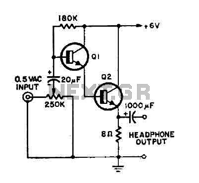
This is a simple headphone amplifier. Any NPN transistor can be used. The circuit can be powered by a 9V battery. The headphone amplifier circuit serves to boost audio signals to a level suitable for driving headphones. It typically consists...

You can use this powerful amplifier in any small audio project. It is very small (6.5 x 4.5 cm). It outputs 10W and uses a 9V battery. More: Components List R1: 6 Ohm R2: 220 Ohm R3: nothing R4:...

A lens is a custom view of the content in the repository. It can be considered a sophisticated type of list that allows users to view content through the perspectives of trusted organizations and individuals. Class D amplifiers exhibit...
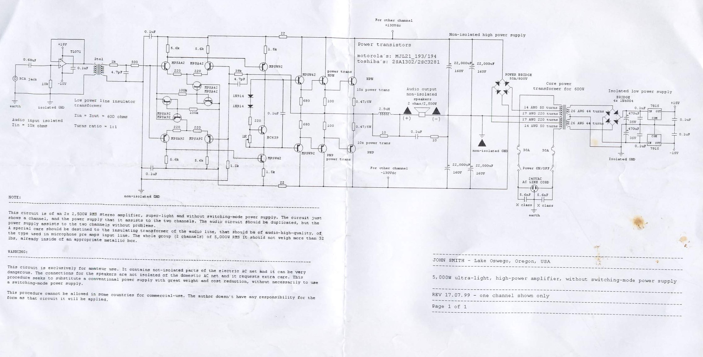
This circuit is for a 2x2, 500W RMS stereo amplifier that is super-light and does not utilize a switching-mode power supply. The circuit diagram displays only one channel, while the power supply is designed to support both channels. The...
Video-DVM is a very cheap DVM that shows how an output as complex as a videocomposite signal can be generated entirely in software: two I/O pins and three resistors are all the hardware required. Connected to any TV set...