
Power Supply for Battery Valve Radios

The described circuit provides a comprehensive solution for powering vintage radios that utilize 7-pin valves, addressing the challenges posed by the unavailability of original battery types. The design leverages a dual-winding transformer to ensure isolation between the HT and LT supplies, thus preserving the integrity of the radio's operation. The voltage quadrupling method, combined with careful decoupling and filtering, ensures stable and reliable high tension supply, while the use of an LM317T voltage regulator for the low tension supply guarantees consistent performance under varying load conditions. This approach not only maintains the functionality of the radio but also enhances its longevity by providing a stable power source, thereby facilitating the continued enjoyment of vintage radio technology.Many later radios use four 7-pin valves and require a 90V HT supply at typically 12mA and a 1. 5V LT supply at 125mA or 250mA depending on the valves used. The original batteries are sadly no longer made. One possibility is to make up a 90V battery using ten PP3 batteries in series for the HT, and to use two D-cells in parallel for the LT. This has the advantage that the set remains portable. However, the cost of the batteries is not insignificant - around £10 even when paying trade prices and probably over £25 if buying retail. The most popular solution is to make up some sort of mains power supply, and a suitable design is presented here.
It should be possible to make the unit for around £30, and the running costs are negligible. Depending on the components used and the size of the battery compartment in your radio, you may be able to make the unit small enough to fit in place of the batteries. The photographs on this page were kindly supplied by Richard Newman, and show his completed unit. Comments, suggestions and modifications made by Richard and a couple of other constructors are given at the end of the page.
To keep the size and cost to a minimum, a single transformer us used to provide both the HT and LT supplies. Since transformers with the correct voltage secondaries are not now available, I have chosen a standard transformer and designed appropriate circuitry to achieve the voltages required.
A 12VA transformer having two separate 15V windings is used. This allows the two supplies to be completely separate. This is necessary because the supplies are generally connected via biasing resistors within the radio, so any connection between them within the power supply would affect the operation of the radio. For this reason, a transformer with two separate 15V windings MUST be used - do not attempt to use a single 15V winding for both supplies.
The HT voltage is not critical, and most sets are designed to operate from around 100V down to about 60V, to get the maximum life from the battery. For this reason, the HT supply on this power supply is not regulated. D1 to D4 and C1 to C4 form a voltage quadruple circuit. I will not attempt to explain the operation here! With any rectifying and smoothing circuit, the off-load voltage will be 1. 414 times the AC RMS input voltage. Therefore, if we quadruple (multiply by four) the 15V AC input, them multiply by 1. 414 we get about 85V. In practice the output from the transformer will be a bit higher than 15V so the output will be around 90V.
R1, C5 and C6 provide some decoupling to eliminate hum. Two capacitors are used in series because 100V capacitors are not so readily available as 63V types. Resistors R2 and R3 ensure the voltage across each of these capacitors is equal. They also discharge the capacitors within a few seconds when the unit is disconnected from the mains. C7 provides additional filtering at higher frequencies. The LT voltage is rather more critical if we are to get the maximum life from the valves. Although the nominal voltage is 1. 5V, the valves themselves will operate down to about 1. 2V. This is to allow the set to keep working as the battery runs down. When operating from a consistent voltage from a mains supply, the LT should be between 1. 3V and 1. 4V. This unit is designed to produce 1. 35V, regardless of the load current. To achieve this, a voltage regulator is used. The output voltage of the LM317T regulator IC is set by the values of two resistors, R5 and R6. The voltage across R5 will be fixed at 1. 25V by the regulator circuitry, so the output voltage of the circuit is a ratio of the two resistor values.
If you wish to change the output voltage, the following formula may be used to calculate the resistor values. "Vout" is the output voltage from the circuit. The value of R5 must be no higher than 240R, so it is generally convenient to leave this at 220R and vary R6 to change the voltage.
🔗 External reference
Related Circuits
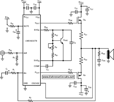
The LME49830 EF125WT1 amplifier PCB module features National Semiconductor's LME ultra-high fidelity power amplifier input stage integrated circuits (drivers). The LME49830 is a fully complementary bipolar 200V input stage IC with a typical output current of 56mA, specifically optimized...
The figure illustrates the voltage-current (V-I) curve for a typical solar panel (Sharp ND-224U1F) and its output power under varying lighting conditions. The solar panel operates as a constant current source at high currents and as a voltage source...
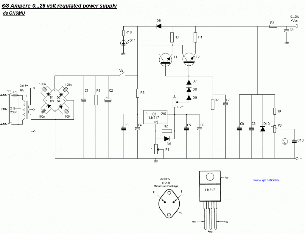
The following diagram is the schematic for a variable power supply that delivers an output voltage ranging from 0 to 28V at a current of 6/8 A. The component part list includes: R1 = 2.2 kΩ, 2.5 Watt; R2...
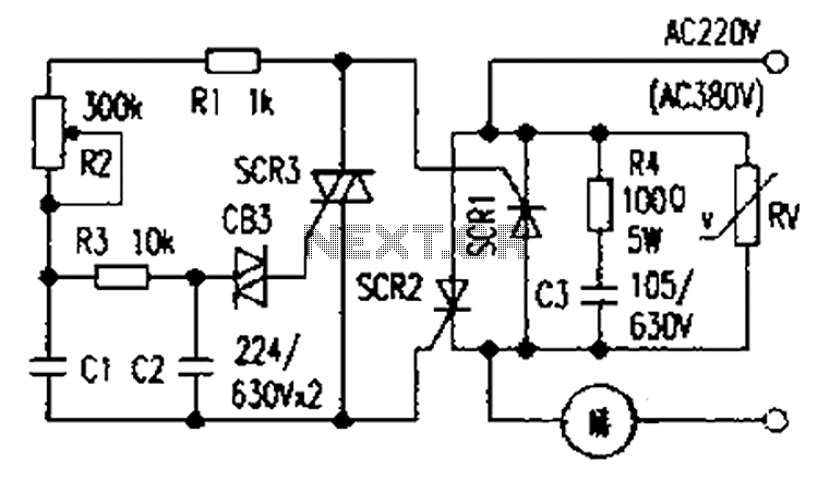
The presentation of a general power thyristor trigger circuit is more complex, and some components are difficult to procure. A successful trigger circuit has been constructed for only a few dollars. This circuit is designed to trigger a thyristor...
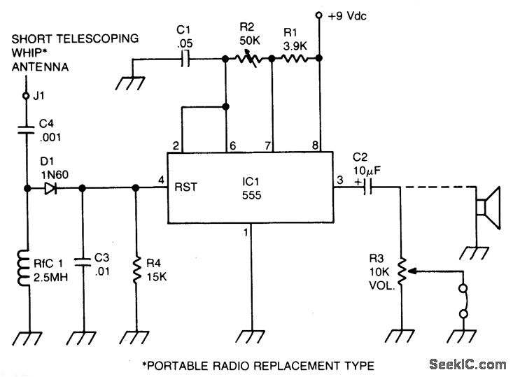
A sidetone oscillator is a specialized audio oscillator that is activated and deactivated in conjunction with the transmitter. This oscillator is driven by RF signals and is powered by batteries. It employs a 555 integrated circuit (IC) timer configured...
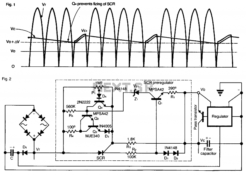
This SCR pre-regulator maintains the filter capacitor voltage (Vc) in a variable output power supply at a few volts above the output voltage (V0). The advantages include reduced heat dissipation by the pass transistor, resulting in a smaller heatsink,...