
Simple and practical power SCR trigger circuit diagram

The described thyristor trigger circuit is designed to manage high-power applications effectively, particularly in industrial settings. Its architecture allows for precise control of voltage and current, making it suitable for applications that require variable speed regulation. The use of SCRs in reverse parallel configuration ensures that the circuit can handle significant power levels while minimizing the risk of damage due to reverse voltage spikes. The incorporation of the potentiometer R2 serves a dual purpose, allowing for both the adjustment of conduction angles and acting as a safety mechanism by blocking current flow when set to a high resistance.
The circuit's ability to generate a DC voltage pulse at the gate of the SCRs without an external power supply simplifies the design and enhances reliability. This feature is particularly beneficial in applications where space and power availability are limited. Additionally, the inclusion of protective components such as the RC snubber and varistor is crucial for maintaining circuit integrity, especially in environments where inductive loads are prevalent. These components help to dissipate voltage spikes that occur during the switching process, thereby prolonging the lifespan of the SCRs and ensuring consistent performance.
Overall, this thyristor trigger circuit represents a practical solution for controlling high-power loads, with its design emphasizing both functionality and protection against common electrical issues. Books presentation general power thyristor trigger circuit are more complex, and some elements hard to buy. I only spend a few dollars made trigger circuit has been successfull y triggered thyristor module above 100A, industrial hardening furnace for regulating voltage 380V, and for installing a set of high-power variable speed blower for use, the effect is very good. This circuit can also be used to adjust 220V AC power supply with electrical appliances. Circuit shown in Figure. The two-way SCR SCRl, SCR2 reverse parallel. Then the control panel connected to this trigger circuit, on the formation of a simple and practical high-power variable speed circuits.
Unique in this circuit is that the SCR gate without external power supply, as long as the load after power is turned on with this series circuit, the two gate between the respective cathode and there 5V ~ 8V DC voltage pulse generation adjustment potentiometer R2 to change two thyristor conduction angle, increasing the resistance R2 to a certain extent, you can make two main thyristor blocked so the R2 also functions as a switch. Another feature of this circuit is that the two main thyristors alternately turned on, a forward voltage drop is another reverse drop, so there is no reverse breakdown problems.
However, when the applied voltage exceeds the transient blocking voltage, SCR1, SCR2 mislead pass, turned extent decided by the potentiometer R2. SCR3 with the surrounding elements constituting the general phase-shift trigger circuit, the principle is omitted here.
SCR1, SCR2 I use is packaged SCR module (110A/1000V), SCR3 selection BTl36, namely 600V triac. This circuit is used as an inductive load, should increase R4, C3 RC snubber circuit and varistor RV for overvoltage protection, preventing the load off and on instantly generate high induced voltage damage to the SCR.
Related Circuits
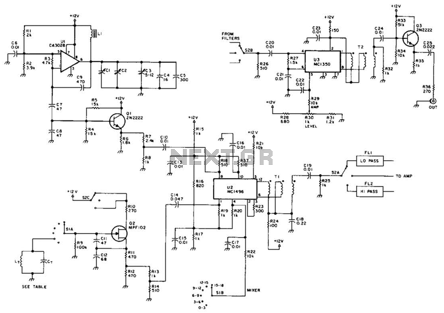
This circuit utilizes a voltage-controlled oscillator (VFO) operating in the frequency range of 15 to 18 MHz (U1), which feeds into a balanced mixer (U2). A fixed oscillator signal is combined with the VFO output to produce an output...
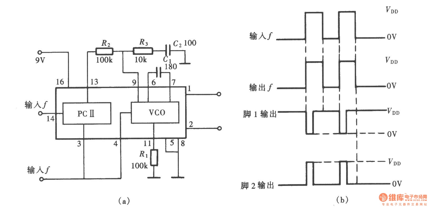
A frequency signal tracking circuit is implemented using a phase-locked loop (PLL) configuration, which is a fundamental application of the CD4046 integrated circuit. The circuit, illustrated in the accompanying chart, utilizes the CD4046 to form a PLL that effectively...
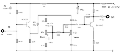
The first BC109C transistor functions as a buffer, delivering a high input impedance of approximately 250k and exhibiting a voltage gain marginally below unity. Given that the Baxendall tone control circuit operates passively, it attenuates all audio frequencies. The...

Below 10 MHz, the development of engineering models is relatively straightforward and not significantly influenced by printed circuit board layout. In the VHF range, parasitic circuit elements and unwanted coupling can severely impact efforts to achieve cost-effective performance without...
The two unspecified polarized capacitors (one directly above the transformer and one directly to the right of the transformer) are actually each a pair of 470 µF capacitors in parallel (for a total of four 470 µF capacitors). These...
This is a high quality power supply with a continuously variable stabilized output adjustable between 0 and 30VDC. The LM 723 is the heart of the power supply which drives the BD137 and then the 2N3055. The circuit provides...