
Power Supply for TTL

A TIC 106A SCR is chosen because it can handle an anode current up to 4A at 100V, but has a very sensitive gate requiring only about 200uA to fire it. The SCR is only on for a very short time and thus does not need a heat sink. If another type is used, it is not likely to display the same characteristics. Most SCRs with a heavy anode current rating have insensitive gates. SCRs with a lower anode current rating will need a heat sink.
The rating of the fuse depends on the power supply used with the circuit. Assuming a maximum power supply output current of about 200 to 300 mA, a 500mA fuse can be fitted.
The voltage at which the SCR switches on is largely dependent on the value of the zener. Different values of zeners can be experimented with to protect other types of circuits. The 4000 series CMOS ICs have supply voltage limits of 15V (AE suffix) or 20V (BE suffix) and crowbar protection can be used for these too.
The described circuit utilizes a zener diode for over-voltage protection, where the zener clamps the voltage at the output to a predefined level (6.2V). The capacitor C4 plays a crucial role in the circuit by providing charge storage, enabling the SCR to trigger promptly when the zener voltage is exceeded. The SCR functions as a crowbar device, effectively shorting the power supply output to ground to protect downstream components by blowing the fuse in the event of over-voltage conditions.
The LM7805 voltage regulator is a standard component in this circuit, providing a stable output voltage of 5V for various electronic applications. Its input voltage range ensures proper regulation, while the associated capacitors mitigate potential oscillations and enhance transient response. The specified input and output capacitors (including the critical 330nF capacitor) must be placed as close to the IC pins as possible to maximize performance and stability.
The choice of the TIC 106A SCR is significant due to its low gate trigger current, allowing for efficient operation without the need for extensive thermal management. The fuse rating must be carefully selected based on the anticipated load current, providing an additional layer of protection for the circuit. Furthermore, experimenting with different zener diode values allows for customization of the over-voltage threshold, making this circuit adaptable for various applications, including those involving sensitive CMOS ICs.In the circuit shown below, if the voltage at the output terminals rises above 6.2V, zener conducts charging capacitor C4. This voltage will fire the silicon-controlled rectifier (SCR), which quickly shorts-or puts a ?crowbar?
? across the supply rails blowing the fuse. The regulator IC is the familiar fixed voltage type such as LM7805. The 7805 is a three-pin regulator which requires a minimum voltage input of 7.5V to sustain stabilization, which an absolute maximum input voltage of 35V. The maximum load current is 1A and the regulation against input changes is typically 3-7mV for a variation of input between 7.1V and 25V.
The regulation against load changes is of the order of 10mV for a change between 5mV and 1.5A load current. The noise voltage in the band from 10Hz to 100KHz is 40-50uV, and the ripple rejection is around 70db.
Maximum junction temperature is 215 degrees C, and the thermal resistance from junction to case is 5 degrees C/W. This stabilizer is used extensively for power supplies in digital equipments. In the circuit, the capacitors that are shown connected each side of the IC are very important for suppressing oscillations and must not be omitted.
In particular, the 330nF capacitor at the input must be wired across the shortest possible path at the pins of the IC. I chose a TIC 106A SCR because it can handle an anode current up to 4A at 100V, but has a very sensitive gate requiring only about 200uA to fire it.
The SCR is only ?on? for a very short time and thus does not need a heat sink. If you use another type, it is not likely to display the same characteristics. Most SCR?s with a heavy anode current rating have insensitive gates. SCR?s with a lower anode current rating will need a heat sink. The rating of fuse depends on the power supply you are using the circuit with. Assuming a maximum power supply output current of about 200 to 300 mA, you can fit a 500mA fuse. The voltage at which the SCR switches on is largely dependent on the value of the zener. You can experiment with different values of zeners to protect other types of circuits. The 4000 series CMOS ICs have supply voltage limits of 15V (AE suffix) or 20V (BE suffix) and crowbar protection can be used for these too. 🔗 External reference
Related Circuits
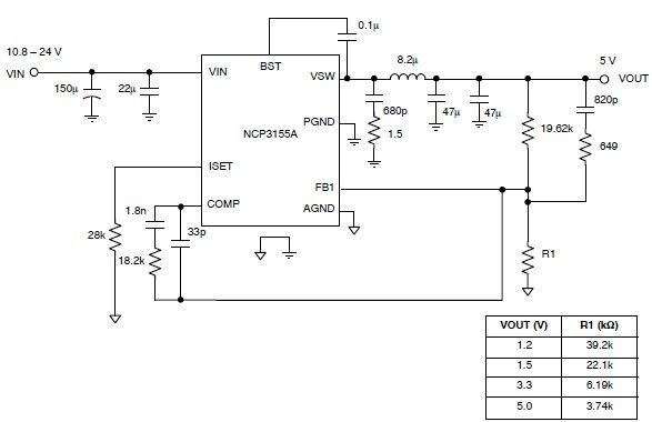
This 5-volt regulated power supply circuit project is designed using the NCP3155 DC-DC switching regulator, which features fully integrated power switches and comprehensive fault protection. The circuit requires only a few external electronic components and delivers a fixed output...
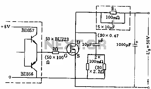
The circuit employs 50 BUZ23 field effect transistors (FETs) arranged in parallel, with a tube blocking voltage of 100V. The control power required is minimal, eliminating the risks associated with second breakdown and the positive temperature coefficient phenomenon in...
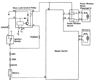
The following circuit illustrates the 1993 Toyota Hilux Pickup Power Window Control System Electrical Circuit Diagram. It is beneficial for both personal use and for mechanics during repairs. Key components include the door lock relay, junction block, power window...
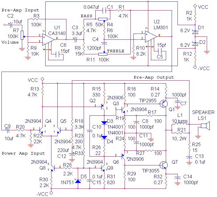
The circuit power amplifier depicted is a schematic design for a power amplifier with an output power of 70 watts, operating in Class AB mode. This power amplifier circuit is equipped with a tone control circuit. The 70-watt power...
This application note describes a digital blood pressure meter concept that utilizes integrated pressure sensor analog signal-conditioning circuitry, microcontroller hardware/software, and a liquid crystal display. The sensing system measures cuff pressure (CP) and extracts pulses for analysis to determine...
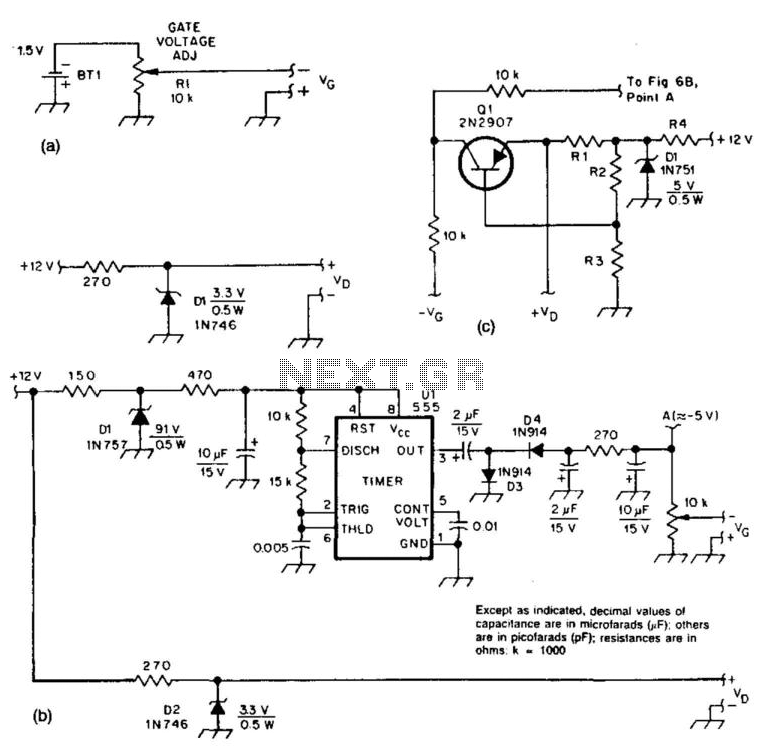
These two circuits provide bias for the microwave preamplifiers discussed in this text. The circuit in Figure 51-5(a) is a simple passive power supply. Figures 51-5(b) and 51-5(c) represent active power supplies, with Ul generating a negative supply and...