
Power Supply Wiring Diagram For Nissan 300ZX

The power supply wiring diagram for the Nissan 300ZX is essential for understanding the electrical system of this sports car. The circuit includes several key components that work together to ensure proper functionality.
The lighting switch is responsible for controlling the vehicle's exterior and interior lighting systems. It connects to the fuse box, which protects the circuit from overcurrent by interrupting the flow of electricity in the event of a fault. The fuse rating should be selected based on the current requirements of the lighting system to prevent damage to the wiring and components.
The ECCS (Electronic Concentrated Control System) is a critical component of the vehicle's engine management system. It regulates fuel injection and ignition timing, ensuring optimal engine performance and efficiency. The wiring from the battery connects to the ECCS, providing the necessary power for its operation. Proper grounding and connections are essential for the ECCS to function correctly, as any interruption in power can lead to engine performance issues.
In summary, the power supply wiring diagram for the Nissan 300ZX encompasses vital components such as the lighting switch, ECCS, and fuse. Each component plays a significant role in the overall electrical system, and understanding their interconnections is crucial for troubleshooting and maintenance.This following circuit shows anpower supply wiring diagram for Nissan 300ZX, sport car called as Fairlady Z. Component: lighting switch,ECCS, fuse .. 🔗 External reference
Related Circuits
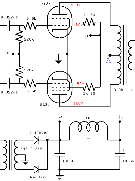
The JCM800 power amplifier has a rich heritage, drawing from classic amplifiers such as the Fender Bassman 5F6-A, the Marshall JTM45, the Model 1962 "Bluesbreaker," and the Model 1987 "Plexi." It features significantly enhanced power supply filtering compared to...
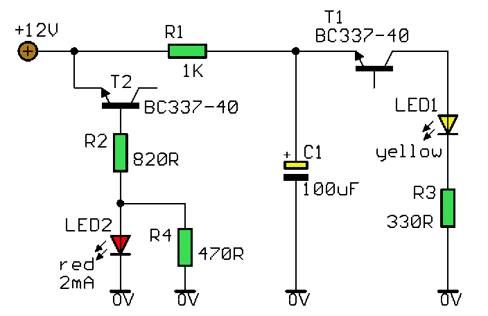
This simple and slightly unconventional circuit provides a clear indication of the supply voltage level in a larger device. When the indicator receives a stable 12 volts at its input, LED1 emits a steady yellow light that appears continuous...
When the input voltage is between 198-242V, the average load current should be maintained at 0.5-1A, and the output voltage must remain at 15V with an error margin of less than 5%. The design and measurement of the stabilized...
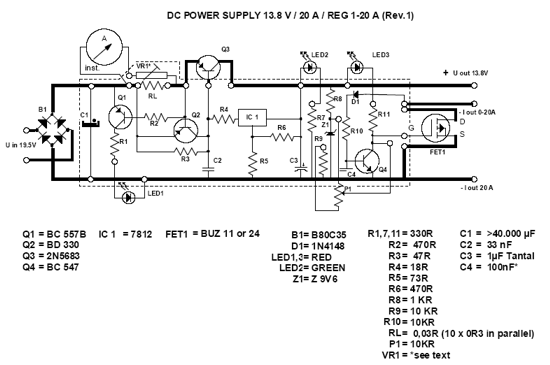
This power supply unit (PSU) is specifically designed for high-current ham radio transceivers. It safely provides approximately 20 Amps at 13.8V. For lower current applications, a separate current-limiting output is available, capable of 15 mA up to a total...
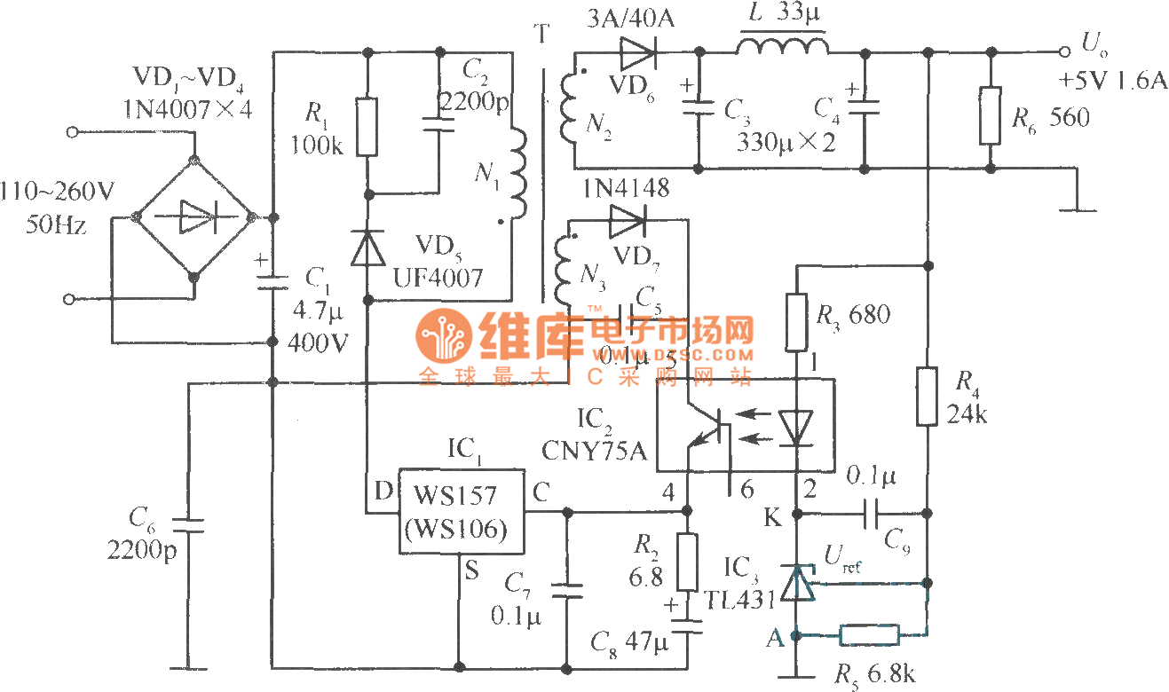
The +5V, 1.6A precision switching power supply circuit is depicted in the figure. This circuit utilizes a photoelectric coupler (CNY75A) and an adjustable precision parallel regulator (TIA31). R3 serves as the current limiting resistor, while R4 and R5 function...
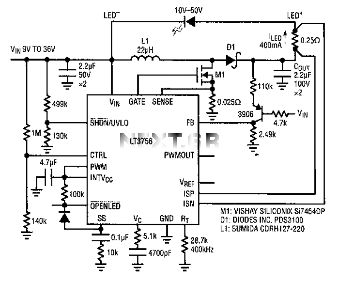
Common LED driver requirements include a wide and overlapping range of LED string voltages and input voltages. Many designers prefer to use an LED driver circuit that accommodates various battery power sources and multiple LED strings. This universal configuration...