
Power tool torque control

The described circuit employs a silicon-controlled rectifier (SCR) to enhance the performance of an electric drill under load conditions. The primary function of the SCR in this application is to regulate the power supplied to the motor as its operational speed decreases. When the drill encounters resistance, such as when drilling into a hard material, the load increases, causing the motor speed to drop. This drop in speed leads to a reduction in back EMF (electromotive force), which is an inherent characteristic of electric motors.
The back EMF serves to oppose the applied voltage and is directly proportional to the motor speed. As the back EMF decreases, the voltage at the SCR gate increases, enabling the SCR to conduct more effectively. This behavior effectively compensates for the loss in torque by allowing a greater amount of current to flow to the motor, thereby maintaining performance despite the increased load.
To ensure optimal thermal management and reliability, it is crucial to mount the SCR on a heat sink made from a thermally conductive material such as aluminum or copper. The recommended dimensions of at least 1 inch square by 0.5 inches thick provide sufficient surface area for heat dissipation during operation. For applications requiring extended use, increasing the size of the heat sink to 2 inches square will further enhance heat management, preventing overheating and ensuring the longevity of the SCR and the overall circuit.
This configuration not only improves the efficiency of the electric drill under load but also contributes to the stability of the operation by maintaining a consistent power output, thereby enhancing the user experience and extending the tool's operational lifespan.As the speed of an electric drill is decreased by loading, its torque also drops. A compensating speed control like this one puts the oomph back into the motor. When the drill slows down, a back voltage developed across the motor—in series with the SCR cathode and gate—decreases. The SCR gate voltage therefore increases relatively as the back voltage is reduced. The extra gate voltage causes the SCR to conduct over a larger angle and more current is driven into the drill, even as speed falls under load
The SCR should be mounted in Vi-in. thick block of aluminum or copper at least 1-in. square. If the circuit is used for extended periods use a 2 inch square piece.
Related Circuits
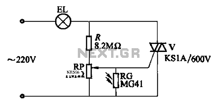
An automatic light control circuit is designed to illuminate a lamp when it is dark and to turn off the light at daybreak. The circuit, as shown in Figure 2-86, employs bidirectional thyristor tubes and features a straightforward design....

This audio amplifier design utilizes TMOS Power FETs configured in a complementary common-source arrangement. The FETs are biased to cutoff and can rapidly turn on when a signal is applied. This design approach offers significant thermal stability in the...
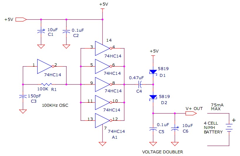
The circuit described will trickle charge a four-cell pack of AA or AAA NiMH batteries. It draws current from the +5V available from a USB connection and supplies approximately 70mA of current to the battery. This current level is...
The TDA2030 is a monolithic integrated circuit in a Pentawat® package designed to function as a Class AB audio amplifier. It typically delivers up to 14 watts of output power (with a distortion rate of 0.5%) at 14V with...
A 50W isolated forward-converter switching supply for telecom applications is described. Most aspects of the design are discussed. The 50W isolated forward-converter switching supply is engineered to meet the specific demands of telecom applications, where reliability and efficiency are paramount....
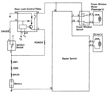
The following circuit illustrates the 1993 Toyota Hilux Pickup Power Window Control System Electrical Circuit Diagram. It is beneficial for both personal use and for mechanics during repairs. Key components include the door lock relay, junction block, power window...