
Automatic light control one lamp lighting circuit b

The automatic light control circuit utilizes a photoresistor (light-dependent resistor) to detect ambient light levels. When the light intensity falls below a certain threshold, the photoresistor's resistance increases, triggering the thyristor to conduct and illuminate the lamp. Conversely, during daylight, the resistance of the photoresistor decreases, causing the thyristor to turn off and extinguish the lamp.
In the first configuration (Figure 2-86 (a)), the capacitor C plays a crucial role in stabilizing the circuit's operation. If the circuit experiences flickering, increasing the capacitance can help smooth out the voltage fluctuations, providing a more stable operation. This adjustment is essential for ensuring reliable performance, particularly in environments with varying light conditions.
The second configuration (Figure 2-86 (b)) incorporates a potentiometer RP, allowing users to fine-tune the brightness of the lamp. This feature is beneficial in applications where different illumination levels are desired, such as in night lights, where a softer glow may be preferable. The ability to adjust brightness enhances the versatility of the circuit, making it suitable for various lighting applications.
Overall, this automatic light control circuit is a practical solution for energy-efficient lighting, providing convenience and adaptability based on the surrounding light conditions. The simplicity of the design, combined with the functionality of the components used, makes it an effective choice for automatic lighting systems. Automatic light control circuit lights automatically illuminate the lamp when dark, lights automatically turn off when daybreak. (1) One of the automatic light control circuit lighting circuit 286 shown in FIG. Both circuits are bidirectional thyristor tube, the circuit is simple. For Figure 2-86 (a). If the photoresistor RG no light when light is off, the capacitor C should be increased capacity. Inadequacies of the circuit in the sense that before each automatic lights on or off flicker. For Figure 2-86 (b), adjustment potentiometer RP, can change the brightness of the light. The circuit can be used as night light use.
Related Circuits
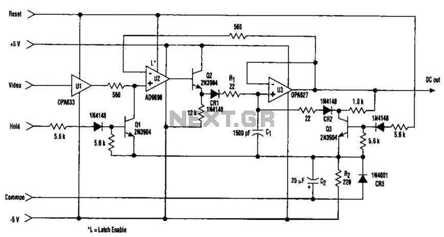
The amplitude of a video signal can be measured using a straightforward circuit that functions as a modified standard peak detector. This device is capable of verifying RGB signals produced by video RAMDACs. U1 is a high-speed buffer, while...
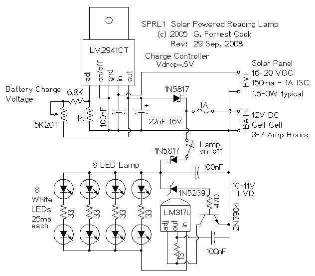
The reading lamp consists of a small solar panel, a standard UPS style lead acid battery, and an LED circuit board. The circuit board contains a low power solar charge controller (regulator), a set of 8 white LEDs, a...
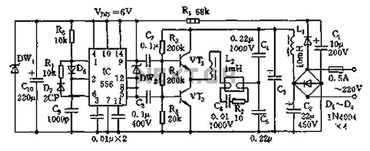
The circuit operates as an electronic ballast for fluorescent lamps, incorporating a rectifier filter circuit, a high-frequency oscillation circuit, and an output circuit. The rectifier filter circuit consists of a rectifier diode (VD1) and filter capacitors (C1, C2). The...
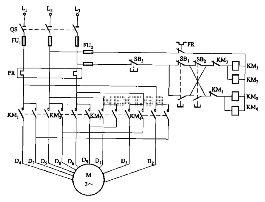
The circuit depicted in Figure 3-112 features two operation buttons: SBi, which serves as the first speed operation button, and SBz, which operates the second speed class. Both buttons facilitate two speeds in the same direction. The circuit design incorporates...
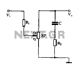
Figure 1-87 illustrates an effective loudness volume control circuit that employs a standard potentiometer. The components used are minimal, yet the performance is notably impressive. The operation principle is as follows: when the internal impedance of the source is...
General Diagram of Motor Controller Manual PDF Download. The motor controller is an essential component in various applications, including robotics, electric vehicles, and industrial machinery. It regulates the operation of electric motors by controlling parameters such as speed, direction, and...