
Powerful LED Flashlight circuit

Reviving the lamp is to determine resistor R1. It should be chosen individually according to amplification factor of the transistor. Temporarily involved trimmer set to the center of resistance pathways and connect the power supply. The recovery is best to use a regulated source, we increase the voltage slowly from 0 to 3.6 to 3.9 V. The maximum LED current one is a short 30 mA lamp current and the power of LEDs would be more than a multiple of this value. To set the trimmer 8 LED current 160 mA (8 of 20 mA). Trimmer vypájíme, measure its resistance and replace a resistor with resistance from the next row. Depending on the desired (small), select the brightness of the resistor R2. It proved to me with about R2, 20 times greater resistance than R1.
Nothing prevents the implementation of other lamps. Involvement can be used for flashlight or headlamp to round. In all cases, at low supply voltage of the LED is practically identical. In connection transistor is in the range of supply voltages from 3.6 to 4.2 in the current change of less than 20%, which is quite sufficient. In fact, the battery voltage during discharge changes very little - most of the time the voltage vybíjeného article in the range 1.2 to 1.3 V. The larger is just only just after charging, smaller, and when the battery is discharged. Involvement of current limiter transistor ( Fig. 2 ) has been described several times. For completeness, I repeat, the current flowing through the transistor determines the collector current to base current amplification transistor. For example, if the LED current 20 mA and the transistor will have a current amplification factor of 100, the required base current 20/100 = 0.2 mA. The resistor is the battery voltage minus the drop in the transition base-emitter (about 0.5 V). Calculate the resistor R = (3,6 - 0,5) / 0,2 = 15,5 Ohm [kOhm, V, mA]. With the change of voltage with current changes in the base, because altering the voltage across the resistor, but this change is smaller than the change of current using a simple serial resistor. I built flashlight in the box DO1-CP, which I shortened to about 10.5 cm. Zaslepíme cover a hole that can make alone and the rest of the box. Glue the lid to the lower part of the box modelá?ským glue on plastic models (for polystyrene). The upper part of the box should be cut a hole above the LED. Due to the high directivity of emitted light is sufficient to have a size corresponding to the area occupied by LEDs on the board. The box should be to remove all tabs and screens in addition to the column, which are connected both parts box. The enclosures can comfortably fit three articles of AA (AA battery). The box is too narrow to fit it into a standard holder. It is best to use a battery "pack" with wire leads. He finished either buy a replacement part for cordless phones, or you can prepare yourself. The lamp power can be used battery composed of three NiCd or NiMH batteries or one Li-ion battery. Li-ion battery is more sensitive to proper handling and considerably more expensive. NiMH batteries in AA now reaches up to 1600 mAh capacity. The collection of 160 mA lamps provide power for 10 hours. The LED lamps can be used with a diameter of 5 or 10 mm. Smaller LED lamp allows zminiaturizovat, tested more LEDs, however, be much more focused light beam (smaller opening angle), which significantly extended the "afterglow". In my lamp I used the larger type.
The described circuit is a straightforward design intended for powering white LEDs using a battery source, specifically three NiCd or NiMH batteries or a single Li-ion battery. The circuit operates efficiently due to the small voltage difference between the battery and the LEDs, which allows for a high percentage of energy utilization. The main components include a series resistor for current limiting and a transistor for controlling the LED current.
The circuit configuration allows for eight white LEDs to be powered, with the LED current being dependent on the supply voltage. The use of a simple transistor circuit is preferred over more complex designs, as it provides sufficient performance without the need for extensive additional components. The circuit design includes a trimmer resistor to adjust the LED current, ensuring optimal brightness while maintaining efficiency.
The assembly is designed for ease of use, featuring solder pads for LED connections and a layout that accommodates modifications for different battery types. The circuit also includes provisions for a switch and jumpers to facilitate user adjustments.
The performance of the circuit is robust, with minimal variation in LED current across a range of supply voltages. The design emphasizes simplicity and effectiveness, making it suitable for various applications, including flashlights and headlamps. The circuit's adaptability allows for the use of different types of LEDs, enabling customization based on specific lighting needs.
In summary, the circuit is a practical solution for LED lighting applications, balancing efficiency, simplicity, and flexibility in design.Presented circuit is very simple. With more sampling, I refrained from using the converter and lamp designed for powering three NiCd or NiMH batteries. Because the voltage difference between the battery and the LED is very small, this arrangement is paradoxically more effective than using the drive.
If the battery voltage of 3.9 V (battery is discharged from about 10%) and the LED voltage 3.5 V, the electrical energy used by 90%, while the efficiency drive from PE 2 / 2000 is in the best case 80%. Remains to choose how to control the current through LEDs. Originally I wanted to stabilize the current circuit, which panned the LED current in a small series resistor Insertion and by deviations from the reference voltage and turning a blind opened the MOSFET. From this project, I eventually withdrew because of this relatively complex circuit would provide little improvement over the simple transistor circuit, which I eventually used.
In Figure A current is flowing eight white LEDs, depending on supply voltage. The first curve shows the LED current, depending on the voltage without any current limitation. It's actually voltampere LED characteristics. The figure shows that the characteristics of the knee is not sharp. Diode really begins to shine it at a voltage of about 2.8 V. In the second case, the current limited resistor with resistance 2.7 ohms, and the third transistor with a resistor to the base - see Figure 2 . Most of the components on a printed circuit board according to Figure 4 and 5 . Outside the plate is only switch S2, which placed it as needed or replace R2 and drop the link. We create the behavior cut into boards for S1. LEDs are soldered to the board stops. Solder pads should be possible Can we shorten the time soldering LEDs to a strict minimum. Instead of engaging temporarily R1 trimmer resistance 5 kOhm resistance (up to 8 LEDs), more preferably in series with a resistor 1 kOhm.
The board is designed so that more skilled at it-yourselfer can riveted contacts for normal cells. But then the board will not fit connector for charging. Jumpers J2 and J3 do not engage! S1 in the box against the left-hand thumb. If it did not meet, the board may make and fitted mirror. Reviving the lamp is to determine resistor R1. It should be chosen individually according to amplification factor of the transistor. Temporarily involved trimmer set to the center of resistance pathways and connect the power supply. The recovery is best to use a regulated source, we increase the voltage slowly from 0 to 3.6 to 3.9 V. The maximum LED current one is a short 30 mA lamp current and the power of LEDs would be more than a multiple of this value.
To set the trimmer 8 LED current 160 mA (8 of 20 mA). Trimmer vypájíme, measure its resistance and replace a resistor with resistance from the next row. Depending on the desired (small), select the brightness of the resistor R2. It proved to me with about R2, 20 times greater resistance than R1. Nothing prevents the implementation of other lamps. Involvement can be used for flashlight or headlamp to round. In all cases, at low supply voltage of the LED is practically identical. In connection transistor is in the range of supply voltages from 3.6 to 4.2 in the current change of less than 20%, which is quite sufficient. In fact, the battery voltage during discharge changes very little - most of the time the voltage vybíjeného article in the range 1.2 to 1.3 V.
The larger is just only just after charging, smaller, and when the battery is discharged. Involvement of current limiter transistor ( Fig. 2 ) has been described several times. For completeness, I repeat, the current flowing through the transistor determines the collector current to base current amplification transistor. For example, if the LED current 20 mA and the transistor will have a current amplification factor of 100, the required base current 20/100 = 0.2 mA.
The resistor is the battery voltage minus the drop in the transition base-emitter (about 0.5 V). Calculate the resistor R = (3,6 - 0,5) / 0,2 = 15,5 Ohm [kOhm, V, mA]. With the change of voltage with current changes in the base, because altering the voltage across the resistor, but this change is smaller than the change of current using a simple serial resistor. I built flashlight in the box DO1-CP, which I shortened to about 10.5 cm. Zaslepíme cover a hole that can make alone and the rest of the box. Glue the lid to the lower part of the box modelá?ským glue on plastic models (for polystyrene). The upper part of the box should be cut a hole above the LED. Due to the high directivity of emitted light is sufficient to have a size corresponding to the area occupied by LEDs on the board.
The box should be to remove all tabs and screens in addition to the column, which are connected both parts box. The enclosures can comfortably fit three articles of AA (AA battery). The box is too narrow to fit it into a standard holder. It is best to use a battery "pack" with wire leads. He finished either buy a replacement part for cordless phones, or you can prepare yourself. The lamp power can be used battery composed of three NiCd or NiMH batteries or one Li-ion battery. Li-ion battery is more sensitive to proper handling and considerably more expensive. NiMH batteries in AA now reaches up to 1600 mAh capacity. The collection of 160 mA lamps provide power for 10 hours. The LED lamps can be used with a diameter of 5 or 10 mm. Smaller LED lamp allows zminiaturizovat, tested more LEDs, however, be much more focused light beam (smaller opening angle), which significantly extended the "afterglow".
In my lamp I used the larger type. 🔗 External reference
Related Circuits
This circuit uses two quad op-amps to form an eight LED audio level meter. The op-amp used in this particular circuit is the LM324. It is a popular IC and should be available from many parts stores. More: The...
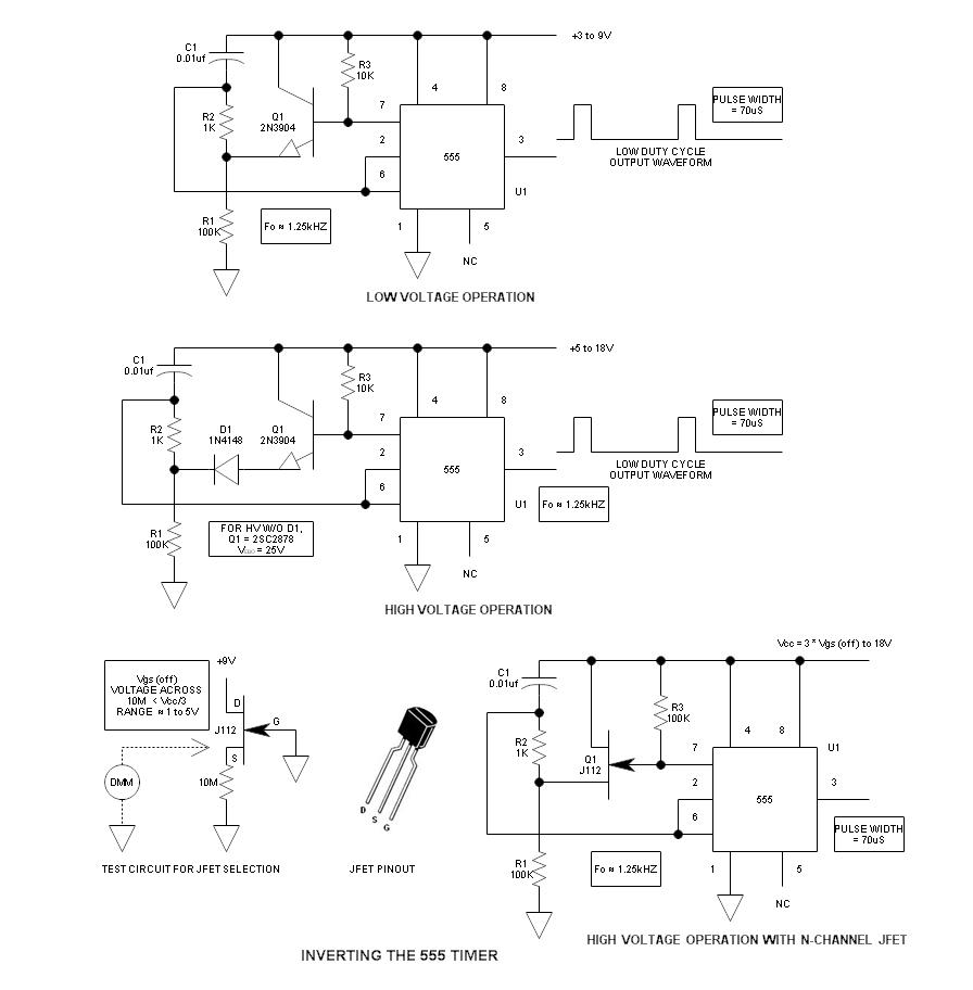
When using the 555 timer, the output polarity often appears to be incorrect, as the 555 typically cannot produce a duty cycle of less than 50%. This inverted 555 circuit is capable of generating duty cycles below 50%. The...
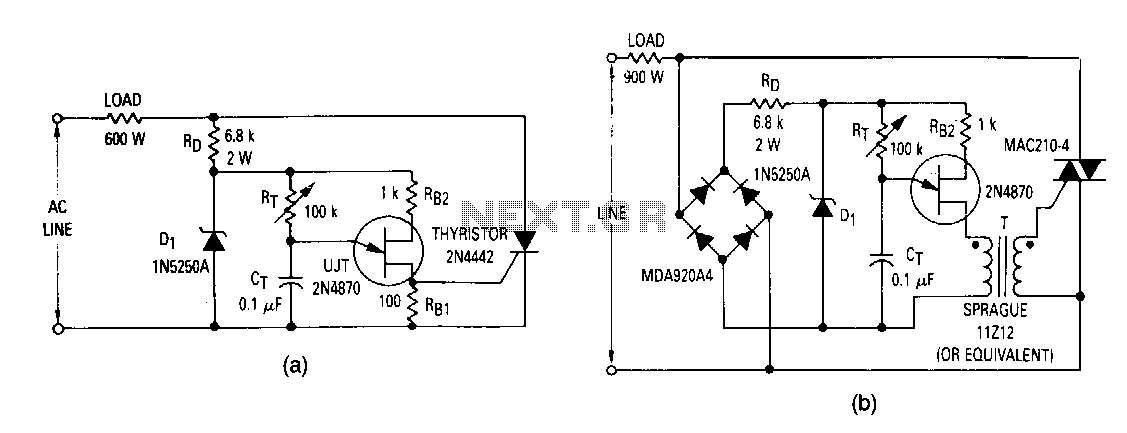
The most elementary application is a half-wave control circuit. The thyristor is acting both as a power control device and as a rectifier, providing variable power to the load during the positive half cycle and no power to the...
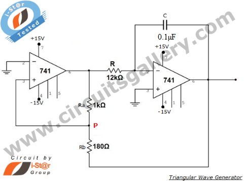
An operational amplifier-based triangular waveform generator is a simple circuit that is widely used in function generators. This circuit utilizes the 741 operational amplifier to create a triangular wave generator. The output waveform of an integrator will be triangular...
The LM1036 is a DC-controlled circuit designed for managing tone (bass/treble), volume, and balance in stereo applications, such as car radios, televisions, and audio systems. It features an additional control input for easy loudness compensation. Four control inputs allow...
A switch that is controlled by its ambient temperature operates without human intervention, except during the assembly of the electronic thermostat. This thermally controlled switch has numerous practical applications. For instance, if the internal temperature of a computer rises...