
powerful security siren

The circuit utilizes a complementary push-pull configuration with transistors Q2 and Q3, which work together to enhance efficiency and output power. This arrangement allows for effective driving of the loudspeaker while minimizing power loss. Transistor Q1 acts as a charge pump, ensuring that capacitor C2 is adequately charged when the circuit is powered on. The gradual discharge of C2 through resistor R8 is crucial for achieving the desired low-frequency oscillation that ramps up to a higher frequency.
The behavior of the circuit is influenced by the values of the components involved. Resistor R8 controls the discharge rate of C2, thereby determining how quickly the oscillation frequency increases. The design choice of using a complementary pair of transistors ensures that both halves of the waveform are amplified, leading to a more robust output signal to the loudspeaker.
When P1 is released, the recharging of C2 through R6 and the base-emitter junction of Q2 provides a feedback mechanism that allows for a smooth transition back to a lower frequency tone. The circuit's ability to halt oscillation once C2 reaches full charge is an essential feature, preventing unnecessary power consumption and allowing the system to enter a low-power standby mode. This functionality is significant in applications where energy efficiency is paramount.
Overall, this oscillator circuit design exemplifies a practical application of transistor technology in audio systems, demonstrating how component selection and configuration can yield efficient performance in sound generation.A complementary transistor pair (Q2 & Q3) is wired as a high efficiency oscillator, directly driving the loudspeaker. Q1 ensures a full charge of C2 when power is applied to the circuit. Pressing on P1, C2 gradually discharges through R8: the circuit starts oscillating at a low frequency that increases slowly until a high steady tone is reached and kept indefinitely.
When P1 is released, the output tone frequency decreases slowly as C2 is charged to the battery positive voltage through R6 and the Base-Emitter junction of Q2. When C2 is fully charged the circuit stops oscillating, reaching a stand-by status.. 🔗 External reference
Related Circuits
The signal begins at a low frequency, increases over a duration of approximately 1.15 seconds to a high frequency, pauses for about 0.35 seconds, and then resumes its ascent from a low frequency, continuing this pattern indefinitely. The described signal...
This circuit is intended for children fun, and can be installed on bicycles, battery powered cars and motorcycles, but also on models and various games and toys. With SW1 positioned as shown in the circuit diagram, the typical dual-tone...
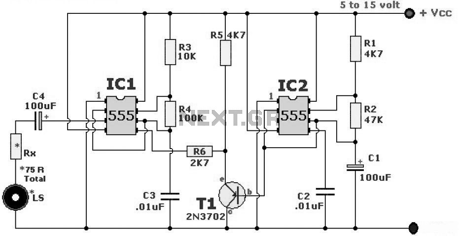
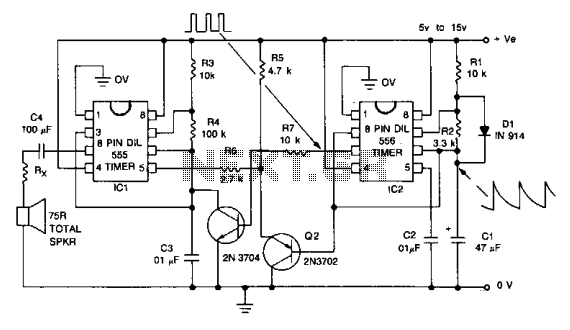
The wailing alarm circuit diagram includes the following component parts: R1 and R5 are 4.7 kΩ resistors, R2 is a 47 kΩ resistor, R3 is a 10 kΩ resistor, R4 is a 100 kΩ resistor, and Rx is specified...
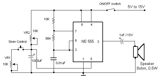
The circuit diagram of an electronic siren based on the NE555 timer produces a sound similar to that of a factory siren. The NE555 timer IC functions as an astable multivibrator with a center frequency of approximately 300 Hz....
This circuit is designed for children's entertainment and can be installed on bicycles, battery-powered cars, motorcycles, as well as on models and various games and toys. When switch SW1 is positioned as depicted in the circuit diagram, it generates...
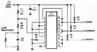
This security system is essential for homes, offices, and factories. It includes a circuit diagram that is simple and easy to construct, making it accessible for anyone. The circuit is cost-effective. Many security systems utilize a closed loop of...