
Siren alarm simulates star trek red alert

The described signal can be implemented as a waveform generator circuit that produces a repeating frequency sweep, mimicking the auditory alert commonly associated with the Star Trek red alert. The circuit can be constructed using a combination of operational amplifiers, resistors, capacitors, and possibly a microcontroller for precise timing and frequency control.
The waveform generator can utilize a triangle or sawtooth waveform to achieve the gradual rise in frequency. The operational amplifier can be configured in a non-inverting mode to amplify the output signal to the desired level. Capacitors and resistors can be selected to define the time constants for the frequency ramp-up and the pause duration. For instance, a resistor-capacitor (RC) network can be designed to achieve the 1.15 seconds rise time by calculating the time constant \( \tau = R \times C \).
To implement the 0.35 seconds pause, a flip-flop or timer circuit can be integrated to control the state of the output signal, ensuring that it remains at a low frequency during this interval. The output could then be fed into a speaker or buzzer to produce the audible alert.
For continuous operation, a microcontroller can be programmed to automate the timing cycles, allowing for precise control over the frequency transitions and pauses, thus ensuring the signal pattern repeats indefinitely. The microcontroller could also allow for adjustments in frequency ranges and durations through software, providing flexibility in the design.
This circuit design can be used in various applications, including alarms, notifications, or any system requiring an attention-grabbing auditory signal. Proper attention to component selection and circuit layout will ensure reliable performance and sound quality.The signal starts at a low frequency, rises for about 1.15 seconds to a high frequency, ceases for about 0.35 seconds, then starts rising again from a low frequency, and so on ad infinitum. it sounds like the star trek red alert.
Related Circuits
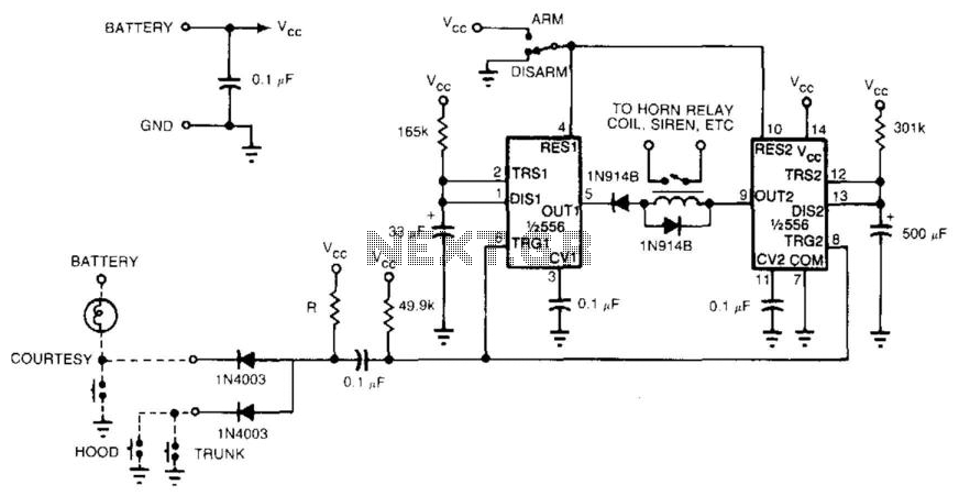
With a single integrated circuit (IC), it is possible to construct a straightforward and dependable auto burglar alarm or a similar alarm system. Refer to (a) for the timing information related to the alarm circuit in (b). When leaving...
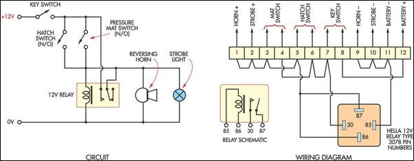
This cost-effective burglar alarm utilizes a 12V strobe light and a truck reversing horn as the visual and audible alarm outputs. The alarm mechanism consists of a 12V horn relay and several pressure mat switches. This straightforward design ensures...
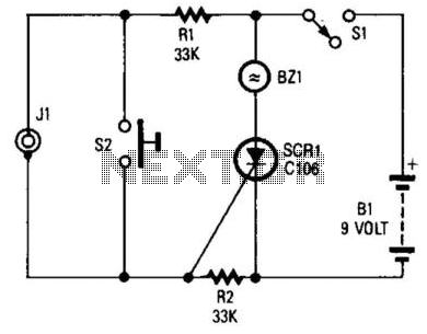
If you choose to create your own moisture sensor, this foil pattern will be useful. A sensor connected to J1 activates CR1, which sounds buzzer BZ1. The sensor consists of a printed circuit board (PCB) foil pattern grid. Multiple...
This infrared light valve has more parts, so it works better and more reliable for alarms. The circuit responds less ambient light. The light valve consists of a transmitter and a receiver. The transmitter consists of a NE 555...
The circuit, as illustrated in Figure 3-82, employs a 555 IC to control a motor automatically, managing its start and stop cycles. The running and stopping times of the motor can be adjusted by modifying the values of potentiometers...

The Basic Alarm Circuit features an automatic Exit/Entry Zone, which includes an Instant Alarm Zone capable of accepting both normally-closed and normally-open triggering devices, alongside an "Always On" 24-hour Personal Attack/Tamper Zone. Expansion Modules can be used to add...