
Single Pushbutton Run-Stop Circuit

In addressing the problem of circuit control, several methods are available, including mechanical, electromagnetic, and electronic solutions. Mechanical solutions typically involve a push On/Push Off switch, which provides a straightforward means of toggling power states. This type of switch is user-friendly and requires no additional components; however, it may not be suitable for applications requiring remote control or automation.
Electromagnetic solutions, such as latching relays, offer an alternative that can maintain their state without continuous power. A latching relay operates by using an electromagnetic coil to toggle between two stable states. This type of relay can be advantageous in applications where power conservation is critical since it does not require a constant power supply to maintain its position.
Electronic solutions, particularly those utilizing CMOS (Complementary Metal-Oxide-Semiconductor) logic, present a highly efficient and versatile option for circuit control. CMOS technology enables low power consumption and high noise immunity, making it suitable for a wide range of applications. A CMOS-based circuit can be designed to perform complex logic operations, allowing for sophisticated control mechanisms that can be tailored to specific requirements.
Each of these solutions has its advantages and limitations, and the choice among them will depend on the specific application requirements, including factors such as power consumption, complexity, and the need for manual versus automated control.There are solutions to this problem—mechanical (push On/push Off switch), electromagnetic (latching relay) and electronic (CMOS logic), but few (if any) go.. 🔗 External reference
Related Circuits
Opamps are very useful. But one of their major drawbacks is the requirement of a dual supply. This seriously limits their applications in fields where a dual supply is not affordable or not practicable. This circuit solves the problem...
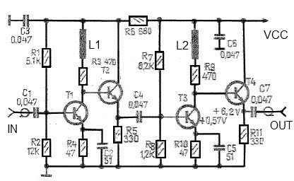
A simple and effective antenna amplifier can be built using the provided circuit diagram. This amplifier is designed for the frequency range of 35 kHz to 150 MHz. It utilizes transistors, offering a low non-linearity of 3 dB and...
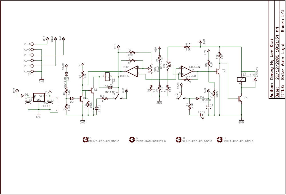
Few years back, I had been working on a project for solar auto lighting. The light will turn on when the solar panel voltage drop below a set point indicating that it is dark. The detection is done by...
Probably the easiest way of doing automatic switch off is with relay logic. In the diagram, the box marked RL1 is the coil, the 2 in the coil box tells you there are two sets of contacts somewhere on...
The Astable Multivibrator, which is generally used as a signal generator, is once again used here to generate the desired frequencies. It is an excellent example of the fact, how versatile simple basic electronic circuit can be. It seems...
This is a simple 50 MHz auto-ranging frequency meter developed as a course project by Simone Benvenuti and Andrea Geniola. It utilizes a single PIC 16C84 microcontroller and four displays to measure frequencies in the range of 0 Hz...