
Pre mic audio amplifier with ic LM386

The circuit serves as a basic audio amplification system designed for applications requiring sound signal enhancement from a microphone. The condenser microphone (MIC1) is responsible for converting acoustic signals into electrical signals. The transistor (Q1) acts as a pre-amplifier, providing initial gain to the weak microphone signal. The collector pin (C) of the transistor outputs the amplified signal, which is then coupled through capacitor C2 to block any DC offset while allowing the AC audio signal to pass.
The variable resistor (VR1) is crucial for adjusting the gain and ensuring that the audio output level is suitable for the application, preventing distortion or clipping of the audio signal. The LM386 integrated circuit is known for its low voltage operation and high efficiency in audio applications. With pin 3 designated as the input, the LM386 receives the amplified signal, while capacitor C3 serves to filter out any high-frequency noise that might interfere with the audio quality.
The output from the LM386 at pin 5 is further processed through capacitor C5 and resistor R5, which work together to eliminate any residual noise and ensure a clean audio signal is sent to the loudspeaker. Capacitor C6 is included to improve the low-frequency response of the audio output, enhancing the overall sound quality before it reaches the loudspeaker.
This circuit is suitable for various applications, including portable audio devices, small public address systems, and other scenarios where compact size and efficient power usage are essential. The use of the LM386 allows for a straightforward design, making it accessible for hobbyists and professionals alike.This circuit be signal sound expansion from condenser microphone give with small-sized loudspeaker. It compose the importance is part pre mic use transistor just one enlarge sound signal gives the power goes up change come to a part amplifier with the integrated circuit LM386 utter go out give aloudspeaker. When feed9V power supplyreach the circui t. The MIC1 and Q1 which be part pre mic, by mic will take sound signal has come in then deliver Q1 enlarge a signal has power size goes up to go out the way collector pin (C) change C2 coupling signal. Then deliver with VR1 for fine signal sound level gives with Input of IC1. Which IC1 numberLM386be theintegrated circuit amplifies1 watt size has pin 3 are input and have C3 will eradicate source noise with input signal discharge down ground.
When amplify finished will export come to the way output pin 5 by have C5 and R5 eradicate a signal takes to stir go out sound signal will have that to change go to still. The C6 coupling signal and enhance sound quality of low frequency improve. Before reach a loudspeaker makes a noise to come out. 🔗 External reference
Related Circuits

An RF power amplifier is an electronic amplifier used to convert a low-power radio-frequency signal into a larger signal of significant power, typically for driving the antenna of a transmitter. It is optimized for high efficiency, high output power...
The shunt-feedback configuration facilitates the straightforward integration of frequency-dependent networks, enabling a functional and discreet switchable tilt control (optional). When SW1 is in the first position, a gentle shelving bass boost and treble attenuation occur. The central position of...
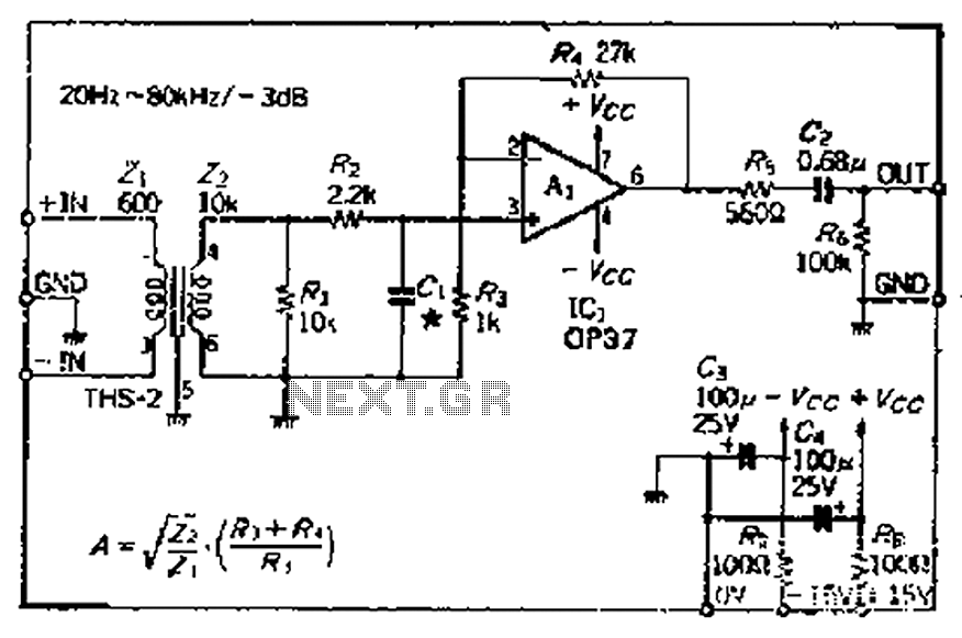
The common mode signal rejection ratio is influenced by the input transformer, which should either be a commercially available or a well-balanced homemade transformer. It is important to note that as frequency increases, the balance may decrease. The transmission...
This article is intended for individuals interested in constructing their own car amplifier. The fundamental calculations will be discussed below. Understanding these concepts will enable the construction of a car amplifier independently. The challenge in designing a car power...
The primary component of this circuit is the LM386 amplifier chip. It also incorporates a transistor input to buffer the input signal and provide additional gain for the LM386. This compact unit has proven useful in various scenarios, particularly...
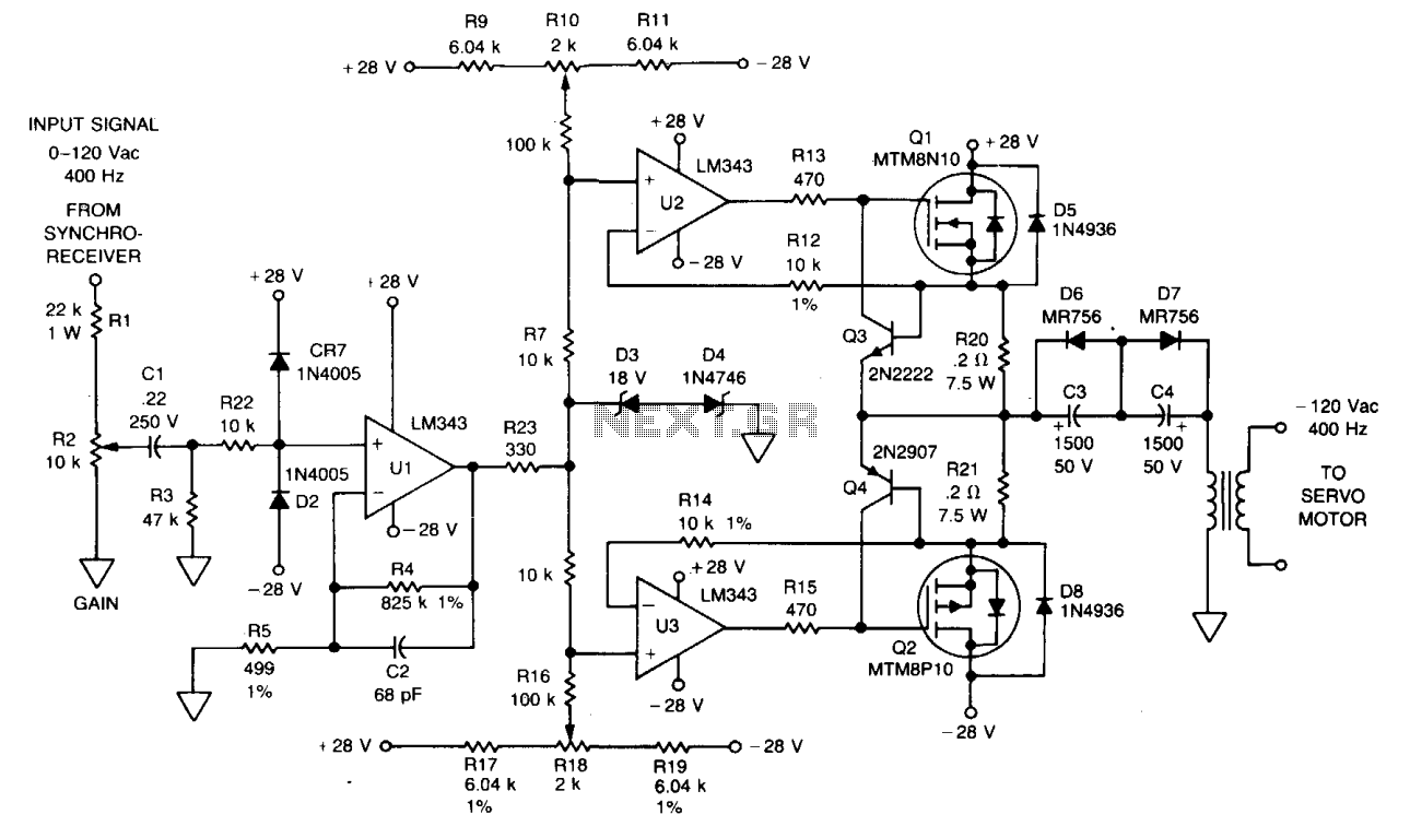
The signal from a synchro receiver or a variable resistive cam follower (potentiometer) is amplified by operational amplifier U1, with its output swing constrained by back-to-back Zener diodes D3 and D4. This amplified signal is then fed into operational...