
preamp HF VHF UHF SHF wideband MAR6

For optimal performance, it is recommended to position the preamplifier as close to the antenna as possible, ideally mounted directly at the feeder (dipole) and utilizing phantom-type powering for the amplifier. The RF/DC splitter should be located inside the shack, just prior to the receiver. It is crucial to maintain short connections at RF IN and RF OUT, ensuring a consistent 50 Ohm impedance starting from the IC leads. The device should be housed in a shielded enclosure.
When used in conjunction with a transceiver, the preamplifier offers a degree of protection against accidental transmission (up to +/- 5 watts) at the output; however, no guarantee is provided that the MAR-6 will withstand such conditions. Precautions should be taken to prevent damage when used in a transmitting scenario (e.g., between the antenna and transceiver). An RF-sensing circuit is recommended for this purpose.
If the antenna already incorporates a static bleeder (or is DC shorted, such as a folded dipole), the inductor L2 can be omitted. To verify this, an ohmmeter can be used to measure the resistance between the center conductor and the braid of the coax, which should read below 1 kΩ. Inverted parallel diodes may also be employed to dissipate static buildup, and testing with a diode tester is advisable. Occasionally, older types of RX verticals may utilize a neon bulb, which cannot be measured; thus, keeping L2 in place is advisable as it poses minimal risk in the aforementioned scenarios.
Connections should be kept as short as possible at RF IN and RF OUT, maintaining a consistent +/- 50 Ohm impedance starting from the leads, and the device should be installed in a shielded casing to minimize interference and enhance performance.The MAR6 (MSA-0686, 0685, 0885) is a high performance silicon bipolar Monolithic Microwave Integrated Circuit (MMIC) housed in a low cost, surface mount plastic package. This MMIC is designed for use as a general purpose 50 W gain block. Applications include narrow and broad band IF and RF amplifiers in commercial and industrial applications.
The MS A-series is fabricated using HP ’s 10 GHz fT, silicon bipolar MMIC process which uses nitride self-alignment, ion implantation, and gold metallization to achieve excellent performance, uniformity and reliability. The use of an external bias resistor for temperature and current stability also allows bias flexibility.
It is a Cascadable Silicon Bipolar The best place to put a pre-amplifier is with out a doubt as closest to the antenna as possible. If possible, directly mounted at the feeder (dipole) and using phantom-type powering of the amplifier.
The RF/DC splitter comes inside the shack just before your receiver. Keep the connections as short as possible @ RF IN and RF OUT and keep them in 50 Ohms impedance starting at the leads from the IC. Mount it in a shielded casing. With use with an transceiver: This preamp is protected to a certain degree for accidental TX (+/- 5watt) at the output, but no guarentee is given that your MAR-6 will survive.
So make the needed precautions to prevent this from occuring when used in a TX type situation (like between your antenna and transceiver). Use a RF-sensing circuit instead. L2 can be left out if your antenna has already some type of static bleeder build in (or DC shortened, like a folded dipole etc.
). If you don`t know for sure, just take your Ohm-meter and measure between the centre and the braid of the coax which should read something like < 1k or so. Inverted parallel diodes are also used to bleed of static build up. Test this with your diode tester. Ever so now and then (mostly with older type of RX verticals) a neon bulb is used hence never can be measured.
Just leave L2 as it is (can`t do much harm in any case stated above anyway). Notes: keep the connections as short as possible @ RF IN and RF OUT and keep them in +/- 50 Ohms impedance starting at the leads. Mount it in a shielded casing. 🔗 External reference
Related Circuits
This circuit is designed for use with inductive pick-up elements and dynamic microphones. Most soundcards feature a line input and a separate input for electret (condenser) microphones. To connect an inductive tape recorder head or a dynamic microphone, an...
This is a simple phono preamplifier circuit diagram. In recent years, following the introduction of CDs, vinyl recordings have almost disappeared. Nevertheless, a phono preamplifier remains useful for listening to old vinyl discs from a well-preserved collection. This simple...
Both transistors should be low noise types. In the original circuit, BC650C was used, which is an ultra-low noise device. These transistors are now hard to find, but BC549C or BC109C are good replacements. The circuit is self-biasing and...
This schematic illustrates a highly sensitive microphone preamplifier circuit designed to amplify the gain of a microphone or enhance audio signals originating from a microphone. The circuit is straightforward, comprising only a few components, and can be assembled in...
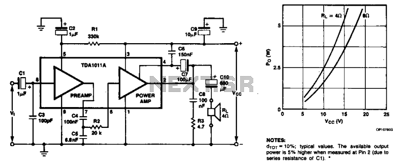
The monolithic integrated audio amplifier circuit is specifically designed for portable radio and recorder applications, delivering up to 4 W into a 4-ohm load impedance. The power output is close to 6 watts RMS. The monolithic integrated audio amplifier circuit...
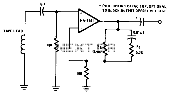
The preamplifier is designed to offer a low-frequency boost at 50 Hz, maintain a flat response up to 3 kHz, and attenuate high frequencies above 3 kHz. Compensation for variations in tape and tape head performance can be accomplished...