
microphone preamp circuit

The microphone preamplifier circuit is designed to provide a significant boost to low-level audio signals from microphones, making it an essential component for audio recording and amplification systems. The use of the 2N3904 transistor ensures reliable performance, as it is capable of handling moderate current levels while providing adequate gain.
The circuit layout typically includes an input stage where the microphone signal is fed into the base of the transistor. The 10K potentiometer is strategically placed in the circuit to control the amount of gain applied to the input signal, allowing users to tailor the amplification based on their specific requirements. The output of the transistor is connected to a coupling capacitor to block any DC offset from the output signal, ensuring that only the amplified AC audio signal is sent to subsequent stages or devices.
Power supply considerations are critical for this circuit, as it can operate within a range of 3 to 9 volts DC. This flexibility allows it to be powered by various sources, including batteries and power adapters, making it suitable for portable applications.
Overall, this microphone preamp circuit is an effective solution for enhancing audio signals, and its simplicity and component availability make it an ideal project for both novice and experienced electronics enthusiasts.Here is a schematic of a very sensitive microphone preamp circuit, which can be used to increase gain of microphone or boost the audio signals coming from microphone. The circuit is very simple contains only few components and can be assembled in few minutes if all parts are available.
This is a versatile mic preamp circuit and can be used for man y purposes. The 10K potentiometer is used in the circuit to increase or decrease the gain. Transistor 2N3904 is a general purpose transistor. The circuit can be operated between 3 to 9 volt DC. 🔗 External reference
Related Circuits
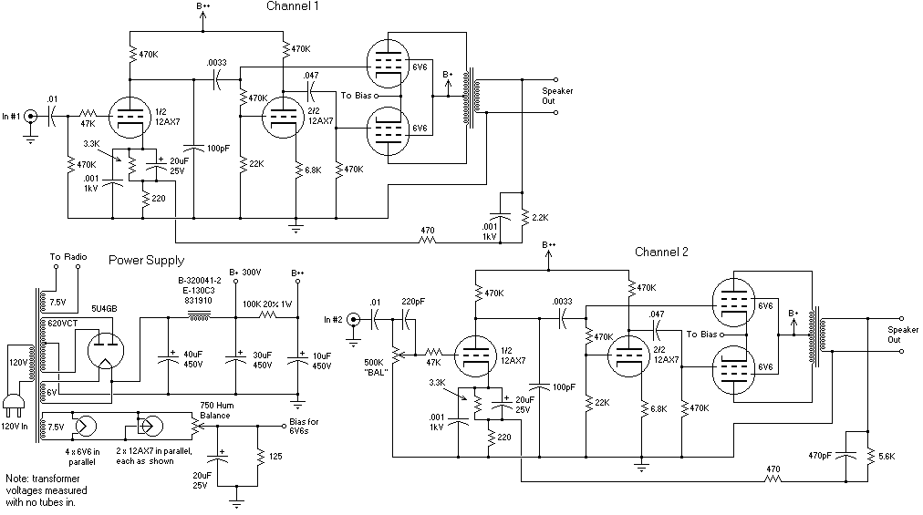
The recommendation regarding the existing phono connector is to maintain its current configuration without making significant alterations. The procedure involves replacing the electrolytic and paper capacitors, adding a three-wire line cord, and utilizing the radio in its original state....
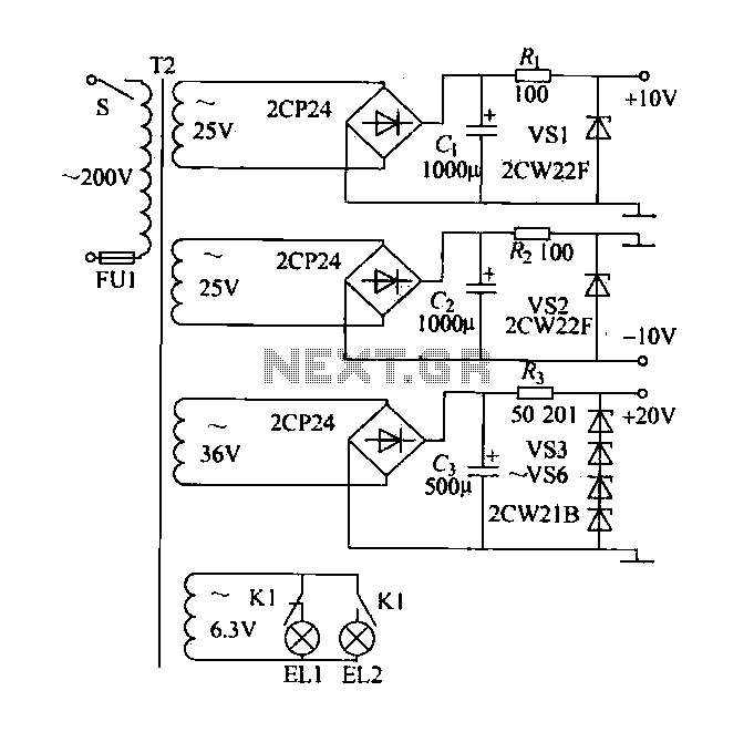
A DC power supply with a shunt, rectifier, filter, current limiting, and voltage regulation, providing 10V voltage outputs. The circuit is simple and low cost, designed to meet the requirements of various applications. Additionally, it features a 3V indicator...
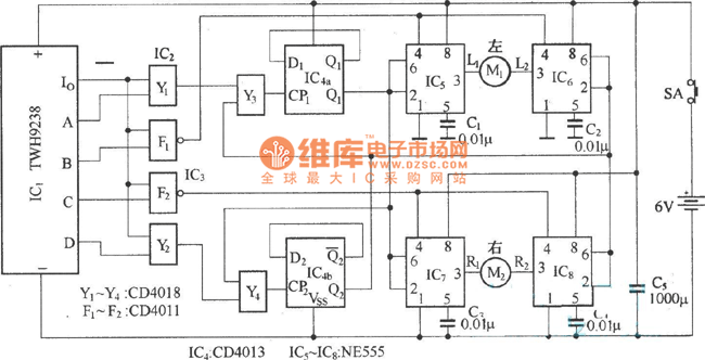
The electric car remote control circuit diagram enables the model car to move forward and backward, as well as turn left and right. It is simple and easy to operate. The radio remote control receiver demodulation circuit utilizes TWH9238...
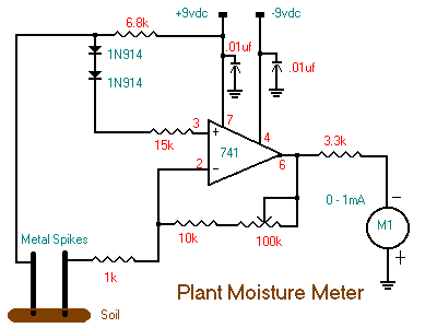
The following circuit illustrates a Plant Moisture Meter Circuit Diagram. This circuit is based on the LM741 integrated circuit (IC). Features include a meter that indicates moisture levels. The Plant Moisture Meter Circuit utilizes the LM741 operational amplifier to measure...
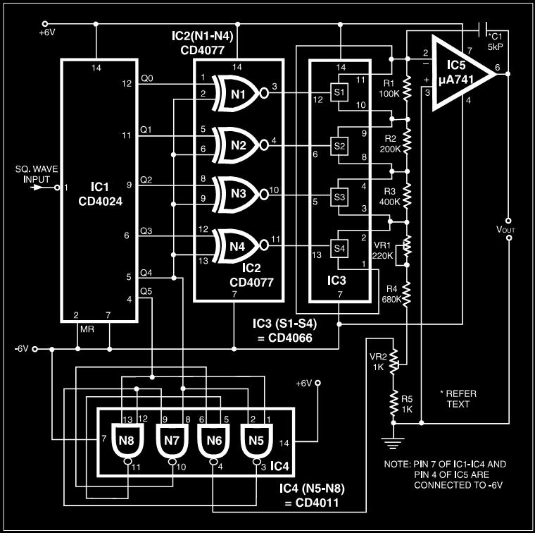
Many electronic devices rely on the shape of signals. Generating square wave signals from sine waves is relatively straightforward, while the reverse process is more challenging. The static square wave-to-sine wave converter circuit can produce an accurate sine wave...
An easy automatic battery charging circuit is presented, which can automatically power off when the battery is fully charged. This design prevents overcharging. The automatic battery charging circuit operates by utilizing a voltage sensing mechanism to monitor the battery's charge...