
Preamp Transmit-Receive Sequencer Circuit

The circuit utilizes a relay-based system to facilitate the switching between transmission and reception modes, ensuring that the preamplifier is protected from potentially damaging RF signals during the transition. The design typically includes a control circuit that triggers the relay based on the operational state of the radio equipment.
In the reception mode, the mast-mounted antenna preamplifier amplifies weak signals received from the antenna, enhancing the overall performance of the radio system. The preamplifier is strategically placed close to the antenna to minimize signal loss due to cable length.
During the transmission phase, the circuit engages a relay that disconnects the preamplifier from the antenna, effectively isolating it from the high power levels generated by the transmitter. This isolation is crucial to prevent damage to the preamplifier and ensure optimal functionality of the radio system.
Additional features may include LED indicators to signal the current operational mode, as well as additional filtering components to reduce noise and improve signal clarity. The overall design emphasizes reliability and efficiency, making it suitable for amateur radio enthusiasts who require robust performance in their VHF and UHF communications. Proper attention to component ratings and circuit layout is essential to maintain signal integrity and protect sensitive components from high RF levels. This circuit is useful in amateur radio VHF and UHF work where a mast-mounted antenna preamp is used for receiving. The kit controls T-R switching and change-over relay sequencing so that high RF levels are prevented
from accidentally being applied to the preamplifier during switching intervals.
Related Circuits
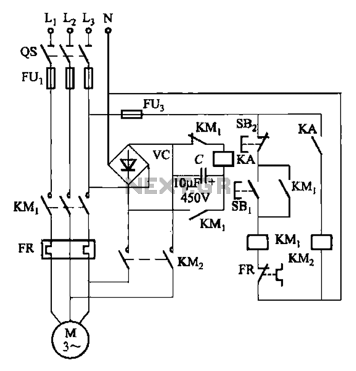
The circuit depicted in Figure 3-137 eliminates the need for a step-down transformer by utilizing the principle of energy storage capacitor discharge for braking. It can be employed to transform the power of motors with a rating of less...
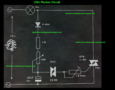
This circuit operates with 230V and can be used to decorate parties. It features a DIAC ER 900 and a TRIAC BTW 11-400. The circuit utilizes a DIAC (Diode for Alternating Current) and a TRIAC (Triode for Alternating Current) to...
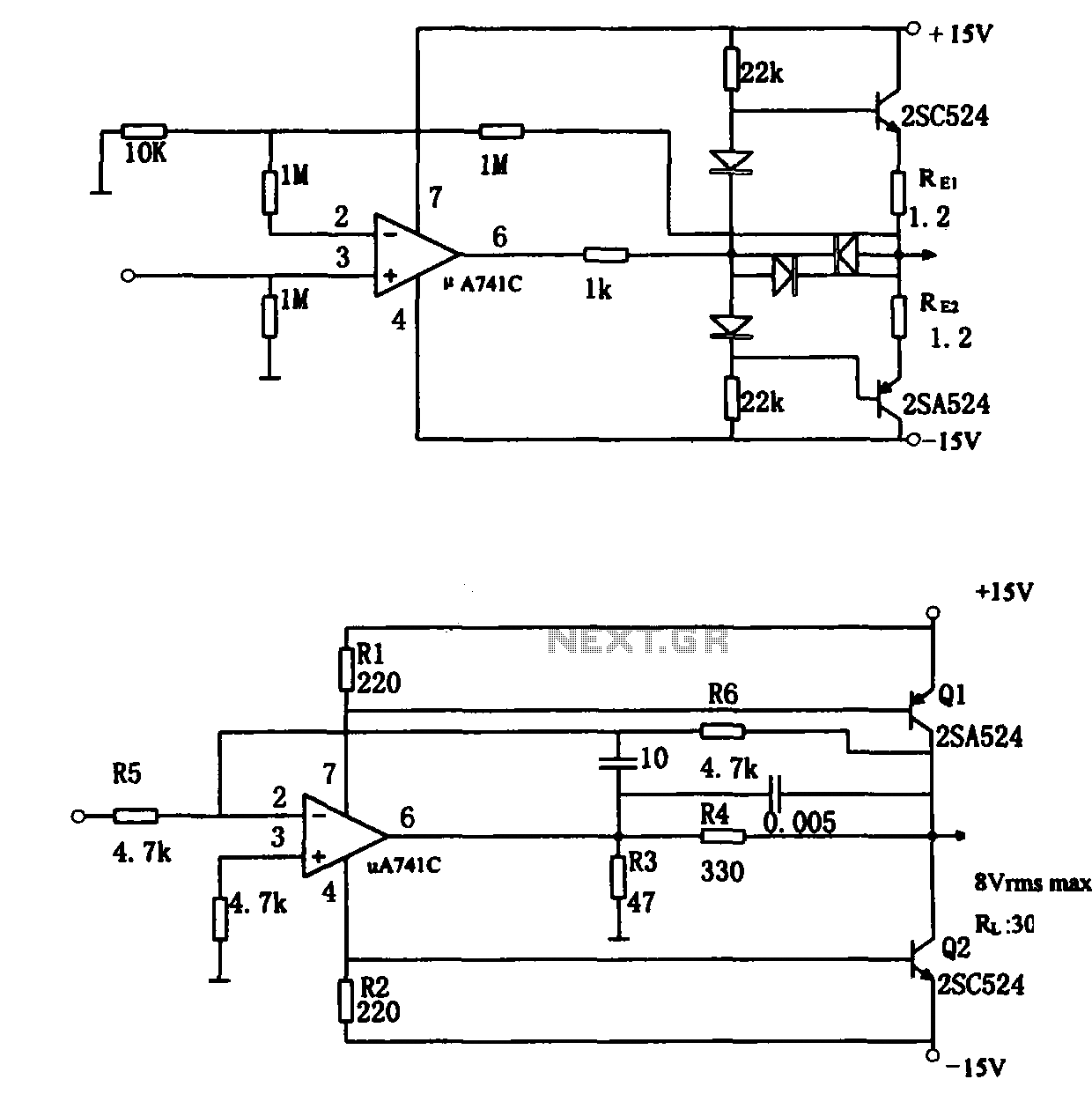
The direct coupling audio power amplifier utilizes an integrated operational amplifier. There are typically two practical configurations. The first configuration, depicted in (a), features a circuit structure that includes the output of the operational amplifier and a complementary symmetry...
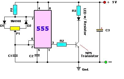
A user is new to the forum and has limited experience in DIY electronics. The current project involves creating a battery-powered LED dimmer circuit. The objective of the project is to design a battery-operated LED dimmer circuit that allows for...
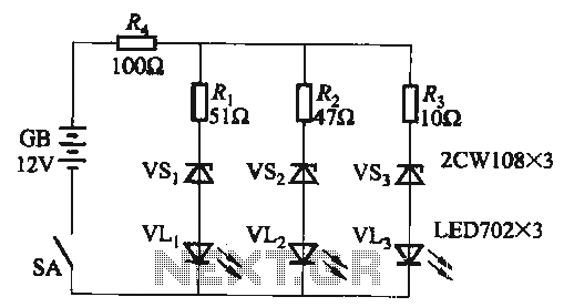
When the supply voltage falls below 10.2V, the yellow light-emitting diode (LED) VLi illuminates, indicating that the storage pool can no longer continue to discharge. Additionally, when the voltage exceeds 16.2V, the yellow, green, and red light-emitting diodes (LEDs)...
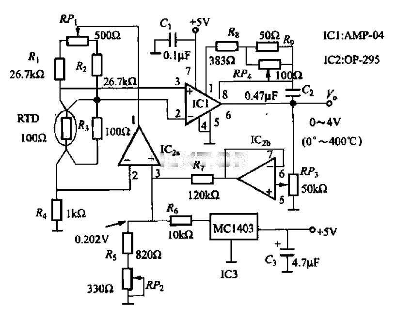
AMP-04 is a single-supply, single resistor gain adjustment circuit with an input voltage drift of less than 150 pV, a current drift of 5 nA, and a temperature drift of 8 pA/°C. The gain nonlinearity is 0.005% of the...