
precision high voltage regulator

This precision high voltage regulator is designed to convert a 9 V input from a battery into a stable 5 V output. The circuit utilizes a switching regulator topology, which is known for its efficiency in power conversion. The regulator achieves an efficiency of 80%, making it suitable for battery-operated applications where power conservation is critical.
The core component of this circuit is the transistor Q1, which serves as the main switching element. When Q1 is turned on, it allows current to flow from the input to the output. The collector voltage of Q1 rises as it conducts, which is essential for maintaining the desired output voltage. The switching action minimizes power loss, as the transistor operates in a saturation region during the 'on' state, effectively reducing heat generation.
To ensure stable operation, additional components such as inductors and capacitors may be integrated into the circuit. These components help filter the output voltage and smooth out any fluctuations caused by the switching action. The inductor stores energy when the transistor is on and releases it when the transistor is off, contributing to the regulation of output voltage.
The output capability of 50 mA indicates the maximum current that the regulator can supply to a load, making it suitable for powering low-power electronic devices. The design can be further optimized by selecting appropriate values for the inductance and capacitance to enhance performance characteristics such as transient response and load regulation.
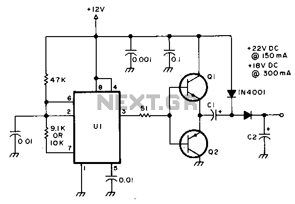
In summary, this high voltage regulator circuit is a compact and efficient solution for converting 9 V battery power into a stable 5 V output, utilizing a simple switching mechanism to achieve high efficiency and reliable performance for various electronic applications.Precision high voltage regulator power supply. Go to that page to read the explanation about above power supply related circuit diagram. This simple switching regulator circuit have 5 V output, the input provide by a 9 V battery. Ithaving 80% efficiency and 50mA output capability. How simple switching Regu lator works: While Q1 is actually on, its collector voltage increases, delivering current. 🔗 External reference
Related Circuits
One of the drawbacks of a three-pin voltage regulator is that the input voltage needs to be 2.5 to 3 V higher than the output voltage. This makes these integrated regulators unsuitable for battery power supplies. For instance, if...
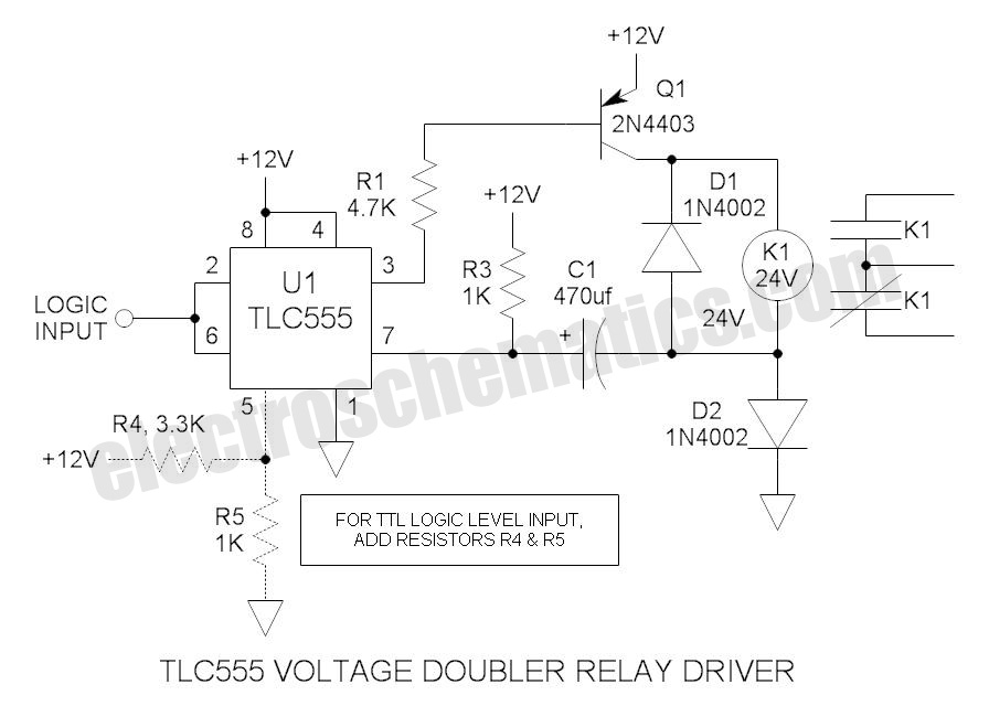
These novel relay driver circuits can activate a relay with a coil voltage rating that is double the Vcc. After activation, the relay armature is held in place. The relay driver circuits described are designed for applications requiring the control...
This circuit operates relays rated for 24V and 18V DC using a 12V power supply. It can be implemented with a wide range of PNP or NPN power transistors. Components include: U1: NE 555 timer; C1 and C2: 50...
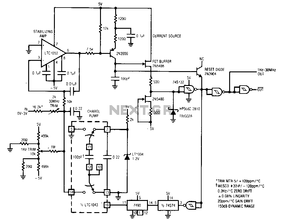
The circuit features a 1 Hz to 30 MHz output with a dynamic range of 150 dB, designed for a 0 to 5 V input. It exhibits a linearity of 0.08% across its entire 71/3 decade range, with a...

This document illustrates the configuration of the high-precision, high-impedance OPA2111 amplifier. The total voltage circuit is designed for a magnification of Av = 10 (1 + 2R2 / R1), achieving a total gain of 1000 times. A gain stage...
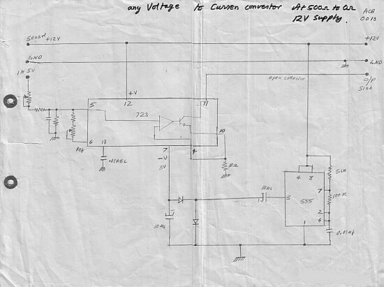
This circuit converts a voltage control output from a process controller into a current control signal, suitable for applications such as AC drives or valves requiring a current control signal. It operates as a three-wire voltage-to-current loop converter. The...