
Pulse width / voltage conversion circuit composed of TL082

The pulse width to voltage conversion circuit operates on the principle of integrating a reference voltage over a specified time interval defined by the input pulse width. The core component of this circuit is the operational amplifier configured as an integrator (A1). The integration process begins when the input pulse is detected, which activates the appropriate switches (S1 and S2) to control the feedback loop.
Initially, when a pulse width of 0.1 seconds is applied, S1 is opened, and S2 is closed, resulting in an output of 0V from the integrator. This state is stable until the input pulse is increased. Once a new pulse is detected, S1 closes, allowing the feedback loop to engage while S2 opens. The integrator then starts to accumulate the reference voltage, which is typically set to a predetermined value that will yield the desired output voltage of 10V after the integration period.
As the integrator processes the input pulse, the output voltage decreases in the negative direction due to the nature of the integration operation. The output will reach a low level once the integration period concludes, indicating that the pulse width has been fully processed. If the input pulse subsequently drops to a low state, S1 is immediately opened, halting the integration process and returning the circuit to its initial state.
This circuit is particularly useful in applications where precise voltage control based on pulse width modulation is required, such as in motor speed control, signal processing, or in digital-to-analog conversion systems. The careful selection of component values, including the resistors and capacitors associated with the integrator, will directly influence the accuracy and responsiveness of the output voltage to changes in pulse width.This is the pulse width (time) / voltage conversion circuit, according to the diagram component parameters, it can convert 0. 1 S pulse width into 10V output voltage. When time pulse input end is added input conversion pulse, the analog switch Sl is disconnected, and S2 is connected, then Al integrator output is OV.
This state has been maintained t o be increased the input pulse. After added pulse, Sl is turned on and S2 is off, and the feedback loop is cut off, then Al makes integral on the reference voltage, and its output reduces in the negative direction and changes into low level at the end of integral. If the input pulse goes low, Sl is immediately disconnected. 🔗 External reference
Related Circuits
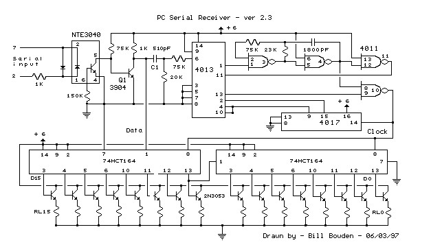
This circuit requires physical connections to be made to the computer's serial port (COM1 or COM2). It is generally considered difficult to cause harm to oneself or the computer through improper connections to this port; however, there is no...
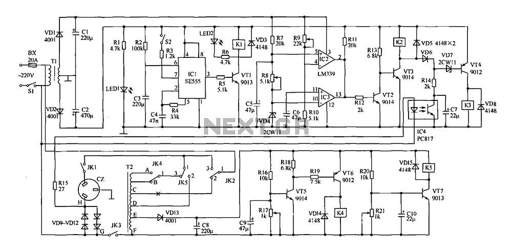
This document presents a power-saving voltage regulator circuit. In addition to its general function as a delay regulator, the circuit features: (1) an automatic voltage regulation capability for mains voltage within a range of 220V ±10%, allowing direct power...
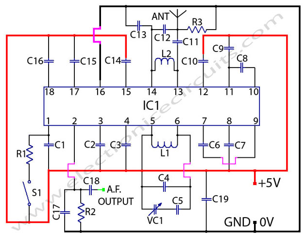
The TDA7000 is a monolithic integrated circuit designed for mono FM portable radios or receivers, emphasizing minimal peripheral components for compact size and cost-effectiveness. This integrated circuit features a Frequency-Locked-Loop (FLL) system with an intermediate frequency of 70 kHz....
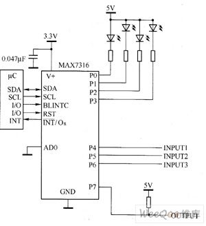
The main technical characteristics of the MAX7316 include a 400 kbps, 2-wire serial interface with a voltage tolerance of 5.5V. The operating voltage ranges from 2V to 3.6V. It features 8-bit PWM control for white LED brightness, with global...
The construction is nearly complete, and a circuit diagram has been created. The design has been finalized and documented on paper. The circuit diagram represents a critical stage in the development of an electronic project, serving as a blueprint for...

This Outdoor LED Solar Garden Lights project is a hobby circuit for an automatic garden light that utilizes a light-dependent resistor (LDR) and a 6V/5W solar panel. During daytime, the internal rechargeable 6 Volt sealed lead-acid (SLA) battery is...