
Precision Measurement without Ground Offsets Using Differential Amplifier Input to A/D ADC

In electronic systems, ground loop offset errors and ground noise can significantly impact the accuracy of measurements, particularly in applications involving non-isolated sensors. To mitigate these issues, a differential amplifier or instrumentation amplifier is employed prior to the A/D conversion process. This approach leverages the differential input characteristics of these amplifiers to reject common-mode signals, which are often the source of ground loop errors.
The differential amplifier configuration typically consists of two input terminals that receive the signal from the sensor and a reference ground. By amplifying the difference between these two inputs while rejecting any signals that are common to both, the differential amplifier effectively eliminates the influence of ground loops. This feature is crucial for maintaining measurement integrity in environments where multiple devices share a common ground.
Instrumentation amplifiers, which are a specialized form of differential amplifiers, provide additional benefits such as higher input impedance and better common-mode rejection ratios (CMRR). These attributes make instrumentation amplifiers particularly suitable for precise measurements in medical devices, industrial sensors, and other applications where accuracy is paramount.
In simpler applications, a basic op-amp circuit can also be designed to remove ground loop errors. This circuit typically includes feedback mechanisms that stabilize the output and enhance the accuracy of the measurement. The schematic for this op-amp configuration may include resistors and capacitors to set the gain and bandwidth, ensuring that the circuit operates effectively in the desired frequency range.
Overall, the implementation of differential or instrumentation amplifiers, along with carefully designed op-amp circuits, plays a critical role in achieving reliable and accurate signal processing in electronic measurement systems. By addressing ground loop errors and noise, these amplifiers enable high-quality data acquisition necessary for modern electronic applications.Ground loop offset errors and ground noise are removed by a differential amplifier or instrumentation amplifier prior to A/D analog to digital conversion. The differential input amplifier mitigates ground loop errors. Precision measurement of non-isolated sensors. Simple op-amp circuit removes ground loop errors. Op-amp schematic removes ground noise.. 🔗 External reference
Related Circuits
This compact amplifier is built around the TDA2003 integrated circuit, which can deliver 4W RMS at a 4-ohm load. The TDA2003 offers enhanced performance while maintaining the same pin configuration as the TDA2002. It retains the advantageous features of...
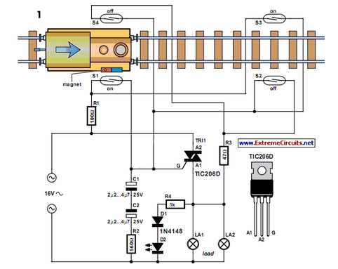
Modern electronics is essential for every large model railroad system, providing solutions to nearly every issue. Although ready-made products are available... Modern model railroad systems rely heavily on advanced electronics to enhance functionality and user experience. These systems often incorporate...
The internal mute circuit and pre-set gain resistors provide a cost-effective design solution. Output power specifications at both 20V and 24V supplies, along with a low external component count, offer significant value to consumer electronic manufacturers for stereo TV...
The test beeper generates a sinusoidal signal with a frequency of 1,000 Hz, which is a standard test frequency for audio amplifiers. It utilizes a Wien-Bridge oscillator configuration, also referred to as a Wien-Robinson oscillator. The frequency-determining network comprises...
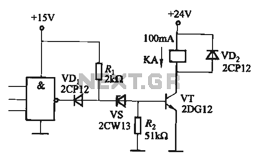
If the CMOS circuit load (actuator) is a relay device, the circuit must have a large load capacity. Non-gate drive switching amplifiers are connected to a separate element shown in the interface circuit. In the context of a CMOS circuit...
The circuit is a microphone amplifier designed for low impedance microphones, approximately 200 ohms. It operates with stabilized voltages ranging from 6 to 30 VDC. If the impedance adapter section with T1 is not constructed, the circuit can be...