
CMOS interface circuit and the switching amplifier

In the context of a CMOS circuit where the load is a relay actuator, it is essential to ensure that the circuit is designed to handle significant load capacities. Relay devices typically require higher current and voltage levels to operate effectively, which necessitates the incorporation of appropriate driver circuits. Non-gate drive switching amplifiers are often utilized in such applications to facilitate the control of these high-power components.
The interface circuit, as referenced in the provided information, is critical for establishing the connection between the CMOS output and the relay. This interface typically includes components such as transistors or MOSFETs that act as switches, allowing the low-power CMOS signals to control the high-power relay operation without direct electrical coupling. This isolation is crucial to protect the sensitive CMOS circuitry from the high voltages and currents associated with the relay load.
The design of the interface circuit should also consider the necessary drive voltage and current requirements for the relay. Proper selection of the switching amplifier is vital to ensure that it can provide sufficient output to energize the relay coil effectively. Additionally, protective components such as diodes may be included to prevent back EMF generated by the relay coil from damaging the switching amplifier or the CMOS circuit.
In summary, when designing a CMOS circuit with a relay load, it is imperative to ensure that the circuit can handle the required load capacity and that the interface circuit is appropriately designed to facilitate reliable operation of the relay while protecting the CMOS components.If the CMOS circuit load (actuator) is a relay device, the circuit must have a large load capacity. Non-gate drive switching amplifiers connected to a separate element shown in FIG interface circuit.
Related Circuits

This is a design of the circuit diagram for an RS422 interface. Connector K1 is connected to the serial port of the PC, and power for the PC side of the circuit is obtained from the signal lines DTR...
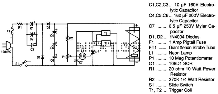
This strobe light operates from standard 120-Vac power. Resistor R1 limits the amount of current applied to the voltage doubler stage, which consists of capacitors C1, C2, C3, and diodes D1, D2, along with capacitors C4, C5, and C6....

These circuits are commonly utilized in robotics to enable DC motors to operate in both forward and reverse directions, as well as to provide an electric brake (short circuit condition). H-bridges can be found as integrated circuits or can...
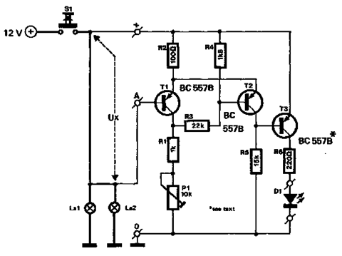
The circuit described below monitors the car's brake lights and indicates their operational status using a 12V light-emitting diode (LED). This functionality can prevent fines for driving with defective brake lights and enhance road safety. The monitor relies on...
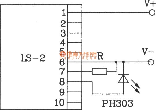
The LS-2 remote control switch infrared sensor module is similar to the LS-18 but functions as a reflector. The LS-2 pin diagram and internal block diagram provide insights into its electrical parameters. The operating voltage for the LS-2 remote...
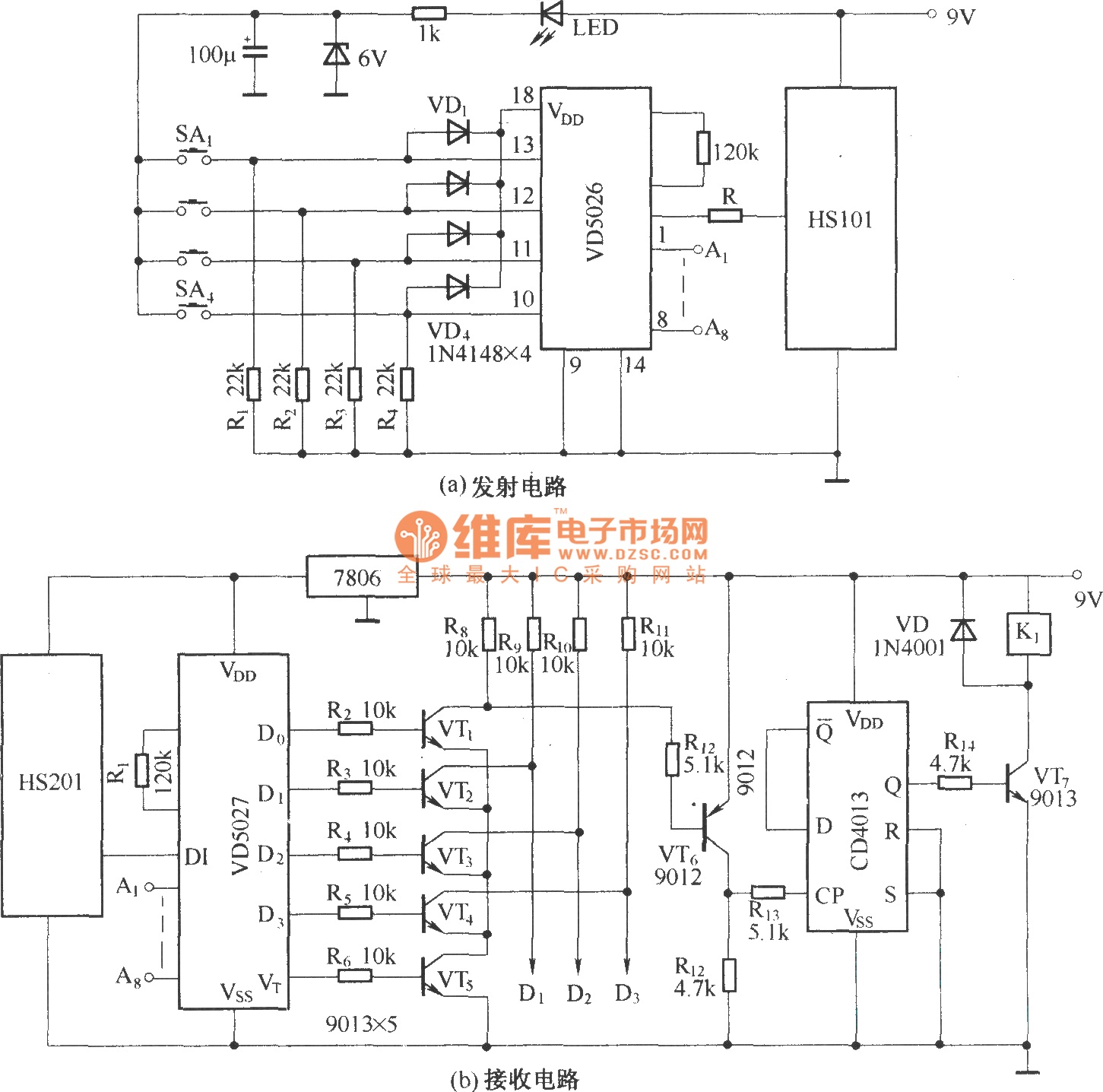
HS101 and HS201 are small radio transceiver components operating at a frequency of 280 MHz, designed for digital signal transmission. They provide a control distance ranging from 30 to 100 meters. All components, including the antenna, are integrated into...