
Low impedance microphone amplifiers

The microphone amplifier circuit is structured to enhance the audio signal from low impedance microphones, which are commonly used in various audio applications. The operational voltage range of 6 to 30 VDC ensures compatibility with a wide array of power supply configurations, allowing for flexibility in different setups.
The inclusion of an impedance adapter utilizing transformer T1 is crucial when working with low impedance microphones. This transformer effectively matches the microphone's output impedance with the input impedance of the amplifier, optimizing signal transfer and minimizing potential signal loss. If the impedance adapter is omitted, the circuit can still function as an amplifier for higher impedance microphones, which typically have an output that can be directly coupled to the amplifier’s input through C7. This capacitor serves as a coupling component, blocking any DC component while allowing the AC audio signal to pass through to the amplifier stage.
The circuit may also include additional components such as resistors and capacitors to set gain levels, filter noise, and stabilize the amplifier's performance. Proper design considerations should be taken into account to ensure that the amplifier maintains a low noise floor and provides sufficient gain to amplify the microphone's output to usable levels for further processing or amplification.
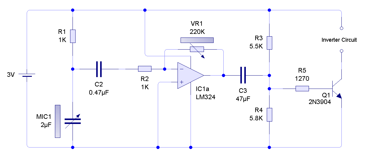
Overall, this microphone amplifier circuit is a versatile solution for audio applications requiring the amplification of low impedance signals, with the added benefit of adaptability for higher impedance microphones when necessary.The circuit is a microphone amplifier for use with low impedance (~200 ohm) microphones. It will work with stabilized voltages between 6-30VDC. If you don`t build the impedance adapter part with T1, you get a micamp for higher impedance microphones. In this case, you should directly connect the signal to C7. 🔗 External reference
Related Circuits
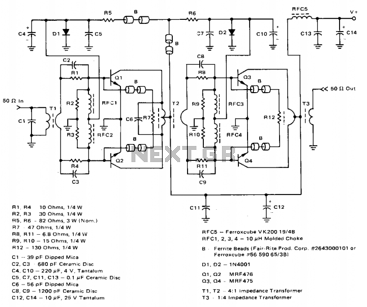
The amplifier achieves a total power gain of approximately 25 dB, utilizing a construction technique that incorporates low-cost components throughout. The MRF476 is rated as a 3-watt device, while the MRF475 delivers an output power of 12 watts. Both...
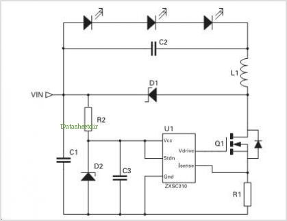
Application of the High Power LED Driver SP7652 with an Analog 0V-to-10V dimmer. Electrical Requirements: Input Voltage of 5.5V to 28V, Output Voltage VF of LED, Output Current ranging from 0 to 6A. This circuit is designed to provide...
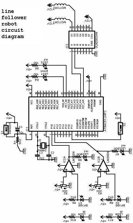
The project involves a line follower robot utilizing the 8051 microcontroller, accompanied by a circuit diagram. A full project report on the line follower or chaser robot is available for download. The line follower robot is designed to autonomously navigate...
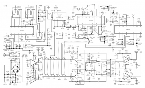
The recent availability of a broad line of truly high-performance consumer integrated circuits makes it possible to construct a high-quality, low-noise, low-distortion electronic system. The emergence of advanced consumer integrated circuits has significantly transformed the landscape of electronic design, enabling...
A ready-made inverter circuit was utilized to drive the EL sheet; therefore, the diagram is incomplete. Additionally, the battery consumption appears to be significantly higher than expected. An AVI video file without sound, recorded using a webcam, is available...
The voltage reference circuit detailed below is a specialized implementation of the LM334 current source. It is characterized by a very low temperature coefficient for the output voltage and consumes only 10 µA at room temperature. This current may...