
Precision Narrow-Band Tone Switch

The described circuit integrates a signal tracker and a lock detector to function as a precision tone switch. The components R3, R4, and C2 form a filter that plays a critical role in defining the signal capture and tracking range, as well as the settling time of the system. The voltage-controlled oscillator (VCO) frequency is adjustable, with the maximum frequency determined by a resistor denoted as R, while the minimum frequency is controlled by the voltage level at pin 9 of the circuit. This pin can range from 0 V to VDD, providing flexibility in frequency modulation.
The lock detector employs a phase comparator (PC) that generates output pulses. The width of these pulses is directly proportional to the phase difference between the two inputs to the comparator. A significant characteristic of the lock condition is that the outputs of the phase comparator become nearly mirror images of each other when the system is locked. In this state, the output of operational amplifier IC1A is low, while the output of IC1B is high. This configuration triggers the illumination of LED1, serving as an indicator of the locked state. Conversely, if the loop is not locked, LED1 will remain off, providing a clear visual cue regarding the operational status of the system.
This design can be utilized in various applications where precise tone switching is necessary, such as in communication systems, audio processing, and signal modulation tasks. The ability to adjust the VCO frequency and the responsive nature of the lock detector ensures that the circuit can adapt to different signal conditions and requirements. This signal tracker and lock detector combine to make a precision tone switch. Filter R3/R4/C2 determines signal capture and tracking range, as well as settling time. Max. VCO frequency: R& Min. VCO frequency: + Pin 9 voltage affects both. The minimum at pin 9 is 0 V and the maximum at pin 9 is VDD. In the lock detector, the PC (phase comparator) outputs are pulses whose width is proportional to the phase difference between the two PC inputs. At lock up, the two PC outputs are almost mirror images. The output of IC1A remains low and IC1B is high. This lights LED1. If the loop is unlocked, the LED will not light.
Related Circuits
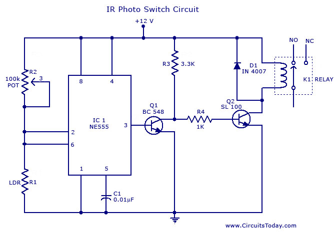
A simple photo switch circuit using the NE555 IC with a diagram and schematic. This photo switch activates a relay when light intensity exceeds a certain threshold. It serves as a light sensor circuit suitable for both home and...
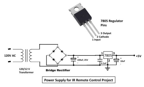
The infrared (IR) toggle switch project aims to provide a control mechanism for electrical appliances lacking remote operation features. The objective is to create a device that allows users to plug in a 120V AC appliance and control its...
A thermally controlled switch operates based on the surrounding temperature without human intervention, except during the construction of the electronic thermostat. This type of switch has numerous practical applications. For instance, it can activate an additional fan when the...
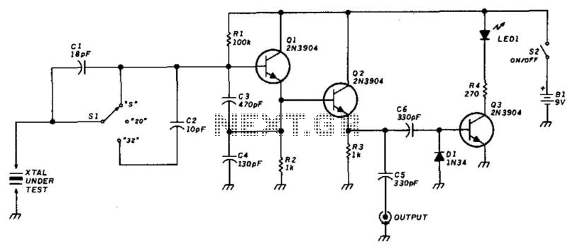
This circuit utilizes a Colpitts oscillator (Q1) paired with a buffer amplifier (Q2) to facilitate crystal testing. SI allows for the selection of three load conditions: series (S), 20 pF, and 32 pF. It is essential to keep the...
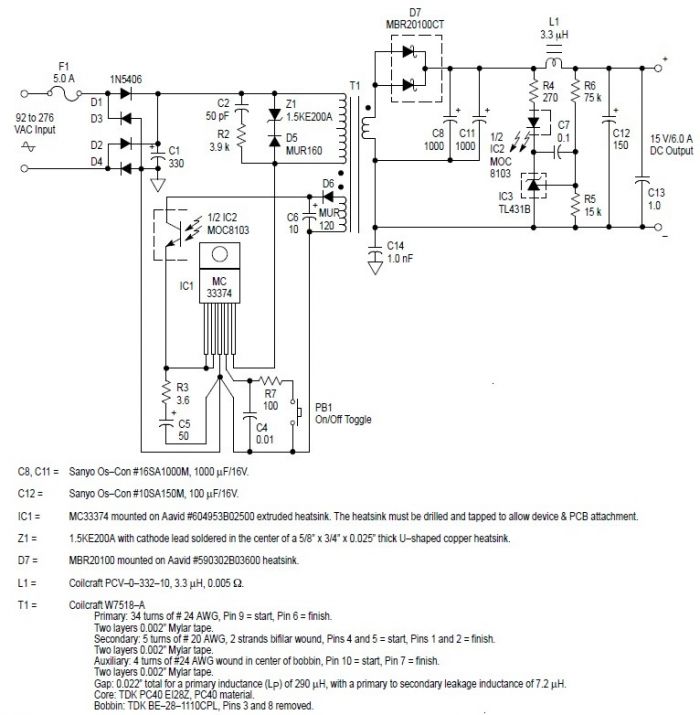
This switching power supply circuit diagram is based on the MC33374 high-power voltage switching regulator IC manufactured by Motorola Semiconductor. The MC33374 switching power supply circuit will provide a maximum output power of around 90 W and requires few...
Nowadays, a switch-off delay for vehicle interior lighting is a standard feature. However, certain models with minimal settings or older vehicles leave users in the dark as soon as they enter and close the door. This situation calls for...