
infrared toggle switch for home

When a key on the remote is pressed, the output of the IR receiver module transitions from high to low, turning the BC557 transistor on and off rapidly. During the ON state, the capacitor charges through the collector current of the BC557, and when the transistor is OFF, the capacitor begins to discharge through the 100 kΩ resistor. However, due to the high frequency of the pulse train (38,000 pulses per second), the capacitor does not have sufficient time to discharge fully. Therefore, each key press from the IR remote generates a positive-going clock pulse at the collector of the BC557 transistor.
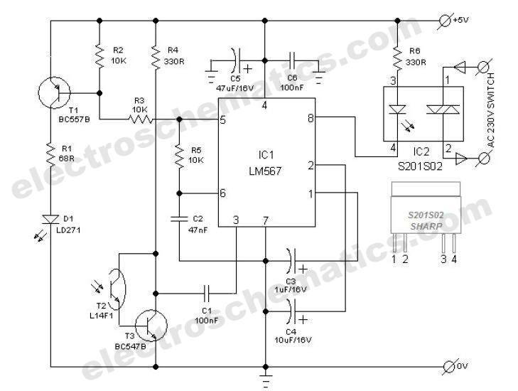
The next component in the circuit is the CD4017 decade counter, which counts low-to-high transitions of the clock pulses received at its CLK pin (pin 14). It can count up to 10 pulses, activating the corresponding output (Q0-Q9) to high. When powered on, Q0 goes high, and upon receiving the first low-to-high pulse (from the IR remote), Q0 goes low, and Q1 goes high. The Q1 output is connected to an LED through a current-limiting resistor to indicate the ON/OFF status. Additionally, the Q1 output drives a relay switch through an NPN transistor (BC547). A 5V DC relay, which requires approximately 70 mA of current from a 5V source to activate, is powered by the BC547 transistor, ensuring reliable operation of the connected appliance.The infra-red (IR) toggle switch project described here is aimed to provide control mechanism for electrical appliances that do not have remote operation features. The goal is to construct a black box where you can plug-in your 120V AC appliance and control ON and OFF operations with any modern IR remote control devices.
Modern IR remote controls generate modulated pulse train of 38KHz frequency when any key on the remote is pressed. With the use of capacitive filtering we will convert the stream of pulses into one pulse regardless of the key entered. This way, we will be able to toggle a relay switch with any key pressed on the remote. This project has been tested with varieties of IR remote control devices like that for TV, DVD, digital camera, etc.
, and it worked well. The TSOP 1738 IR receiver module detects the 38KHz input pulses received from the IR remote control device. Under stand-by condition, the output pin of the IR module is at logic High, and when it detects the train of pulses, they appear at its output.
The output from IR receiver is fed to a PNP transistor (BC557) with a series base resistor of 4. 7K. At the collector of the NPN transistor, the train of pulses will be inverted. There is a 10uF capacitor and 100K resistor connected from the collector to ground. The function of capacitor is to convert the train of pulses into a single pulse, and the resistor is to provide the discharge path for the capacitor. So lets see what happens when a key on the remote is pressed. During standby, the output of IR receiver module is High, so BC557 is cut off. The capacitor is fully discharged, and the collector of BC557 is at ground. When a key is pressed on the remote, the train of pulses arrived at the base of BC557 turns it ON and OFF very fast.
When it is ON, the capacitor gets charged through the collector current of BC557, and when it is OFF, the capacitor starts to dischargethrough 100K resistor. But the train of pulses is so fast (38000 pulses per second) that the capacitor doesn`t get chance to discharge.
So, the bottom line is, every time a key is pressed from the IR remote, a positive going clock pulse is generated at the collector of BC557 transistor. Next comes CD4017, a decade counter. It counts low-to-high going pulses up to 10 that are arrived at its CLK pin (14) and pulls the corresponding output (Q0-Q9) High.
When it is just turned on, Q0 goes High, and when it gets a first low-to-high pulse (when a key is pressed from the IR remote) at CLK i/p, Q0 goes Low and Q1 goes High. Q1 output is connected to a LED through a current limiting resistor to indicate the ON/OFF status. The Q1 output is also used to drive a relay switch through a NPN transistor (BC547). I used 5V DC relay that requires about 70mA current from 5V source to turn ON. This current is provided by BC547. 🔗 External reference
Related Circuits
This is a clap switch designed to avoid false triggering. To activate or deactivate any appliance, a user must clap twice. The circuit changes its output state only when two claps are detected within a specified time frame of...
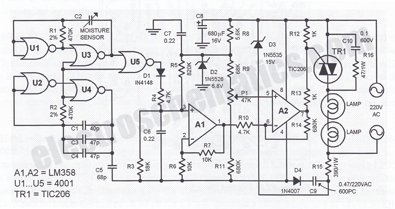
This humidity-controlled switch circuit activates and deactivates an electrical load, such as a heater, based on the moisture content in the surrounding air. The humidity-controlled switch circuit employs a humidity sensor to detect changes in moisture levels in the environment....
The power switch with an infrared proximity sensor is designed to detect obstructions at distances ranging from a few millimeters to several centimeters. The power switch utilizing an infrared proximity sensor operates on the principle of emitting infrared light and...
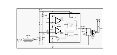
This circuit is designed around a 555 timer and utilizes a minimal number of components. Due to its simplicity, it can be easily constructed and operated by beginners. The circuit leverages the 555 timer IC, which is a versatile and...
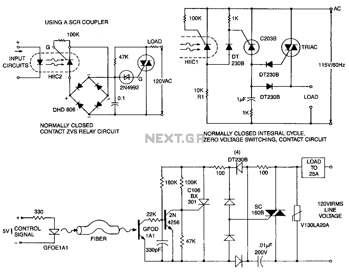
This circuit is effective for lamp and heater loads. Some circuits driving reactive loads require integral cycling and zero-voltage switching when an identical number of positive and negative half-cycles of voltage are applied to the load during a power...
This is an IR transmitting circuit which can be used in many projects. This IR transmitter sends 40 kHz carrier under computer control. The circuit can be controlled using any TTL or RS-232C level control signal which makes the...