
variable voltage controller

The 555 timer IC is a versatile component commonly used in various oscillator and timer applications. In this configuration, the circuit is powered by a +12V supply connected to the VCC pin (pin 8) of the 555 timer, while the ground (0V) is connected to the GND pin (pin 1). The absence of a negative voltage supply simplifies the design and reduces complexity, making it suitable for a wide range of applications.
In a standard astable configuration, the 555 timer can produce a continuous square wave output. Resistors R1 and R2, along with capacitor C1, determine the frequency and duty cycle of the output waveform. The output is available at pin 3, which can drive loads directly or be interfaced with additional circuitry.
The frequency of oscillation can be calculated using the formula:
\[ f = \frac{1.44}{(R1 + 2R2) \cdot C1} \]
where:
- \( f \) is the frequency in Hertz,
- \( R1 \) and \( R2 \) are the resistances in ohms,
- \( C1 \) is the capacitance in farads.
The duty cycle, which represents the proportion of time the output is high versus low, can be expressed as:
\[ Duty \ Cycle \ (\%) = \frac{R2}{R1 + 2R2} \times 100 \]
This configuration allows for a wide range of frequency and duty cycle adjustments by varying the values of R1, R2, and C1. The output signal can be used for driving LEDs, triggering other devices, or generating clock pulses for digital circuits.
Overall, the design of a 555 oscillator powered by a +12V supply is straightforward and effective for generating reliable timing signals in various electronic applications.Ohh ok cool, I have forgotten about the -12 supply because my 555 Oscillator doesn?t use a -12 supply, it only uses a +12 and a Ground. You see on my.. 🔗 External reference
Related Circuits
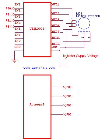
This tutorial utilizes the ATmega8 microcontroller with a 4 MHz crystal oscillator and unipolar stepper motors. The ULN2003, a Darlington pair driver integrated circuit, is employed for motor control. The ATmega8 microcontroller is a versatile 8-bit device from the AVR...
The LM317T is an adjustable three-terminal positive voltage regulator capable of supplying more than 1.5 amps with an output range of 1.25 to 37 volts. The device features built-in current limiting and thermal shutdown, making it robust against failure....
The F84 MRTC was my second design of a miniature real-time controller. This version uses PIC16F84 running with a low power X-tal 32,768Hz. The scheduler for 6-channel output was saved in EEPROM. No terminal for serial downloading of the...
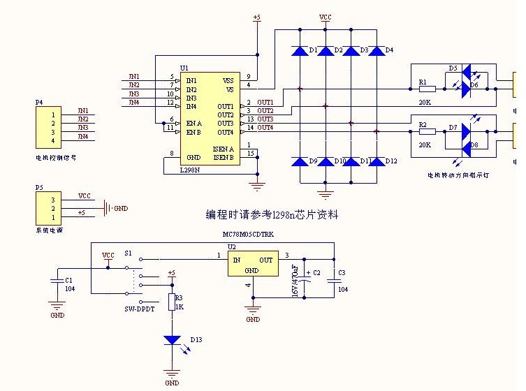
The L298N driver module incorporates the ST L298N chip, commonly utilized to drive two DC motors with voltage ratings between 3V and 30V. It features a 5V output interface that provides power for 5V single-chip circuitry and supports 3.3V...
The iPod Shuffle has malfunctioned, likely due to a failure in the controller chip for the mini jack, resulting in the inability to detect the charger, PC connection, or headphones. The arc must be kept short to minimize distortions...
All miniature electronic devices operate on batteries. Some require higher than standard battery voltages for efficient operation. When a battery of the required voltage is unavailable, additional cells must be connected in series to increase the DC voltage, which...