
PRECISION RECTIFIER

The described circuit operates as a full-wave rectifier using two stages of operational amplifiers to achieve precise signal processing. The first stage employs the 3130 op-amp to perform signal separation based on polarity, effectively allowing the circuit to handle both halves of the input AC waveform. The use of two 10K resistors helps ensure that the op-amp can accurately differentiate between positive and negative signal components, providing a robust method for signal conditioning.
The subsequent stage of the circuit integrates the outputs from the first stage, where the second op-amp combines the rectified peaks. The 5K trimming potentiometer is a critical component for calibrating the circuit; it allows for fine-tuning of the amplitude of the output signal, ensuring that both the positive and negative peaks are matched in height. This adjustment is essential for maintaining accuracy in applications where precise voltage measurements are required.
The output of the second op-amp stage presents a negative-going full-wave replica of the original input signal. This characteristic is particularly useful in digital voltmeter applications, where the goal is to convert the AC input into a stable DC representation. Following this stage, a filtering process is employed to smooth out the output, resulting in an average DC voltage that can be easily interpreted by subsequent measurement systems. The specified range of 0 to -1.5 V for a 0-3 V peak-to-peak input indicates the circuit's capability to handle typical voltage levels encountered in various electronic applications, making it an effective solution for accurate voltage measurement and analysis.Used in digital voltmeters to convert AC waveform to full-waverectified DC equivalent. First 3130 opamp is used as polarity separator, with negative-going signals appearing across upper 10K resistor and positive-going signals across lower 10K resistor. Output of opamp exceeds these voltage drops by exactly diode voltage drop. Second opamp stage re combines positive and negative peaks. 5K trimming pot is adjusted so both peaks are equal height. Output of second opamp is negative-going full-wave replica of input signal. After filtering, output is average DC value in range from 0 to -1. 5 V for 0-3 V P-P input. -D. Lancaster, "CMOS Cookbook, " Howard VV. Sams, Indianapolis, IN, 1977, p 345-346. 🔗 External reference
Related Circuits
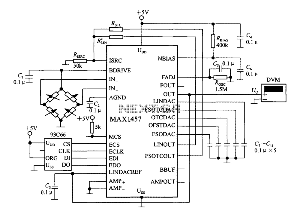
The circuit diagram illustrates a digital precision pressure tester using the MAX1457 integrated circuit with an external ROM selection of the 93C66 type, which is a 4096-bit E2PROM. Upon powering on, the MCS pin is pulled to a high...
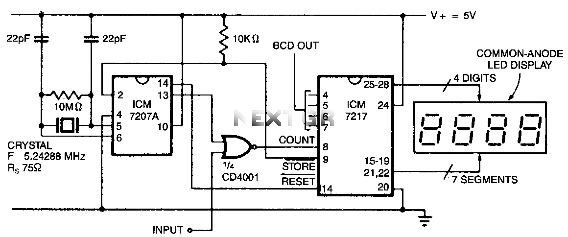
In this configuration, the display shows hertz directly. When pin 11 of the ICM7027 A is connected to V00, the gating time is set to 0.1 seconds, allowing the display to represent tens of hertz as the least significant...
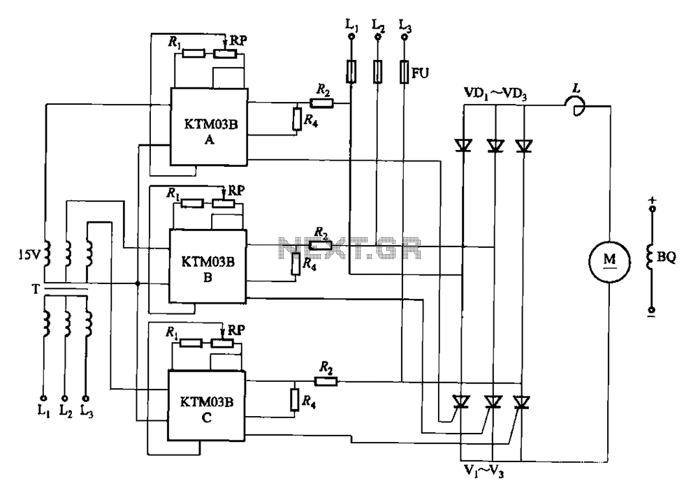
Adjusting the phase potentiometer RP can change the conduction angle of each corresponding thyristor (V1-V). This adjustment alters the voltage applied across the load. The circuit utilizes a phase control technique to manage the power delivered to a load by...

The circuit described is a crystal oscillation circuit using a CM OS inverting configuration, designed to ensure accurate operation. It employs a BCD counter (IC2) capable of achieving a maximum oscillation frequency of 2 MHz, which is 100 times...
The AD8221 is an ideal choice for bridge measurement applications due to its low offset voltage and high common-mode rejection ratio (CMRR) across a wide frequency range. The bridge can be directly connected to the device. The AD8221 is an...
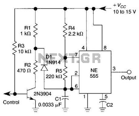
A 1-kHz gated oscillator with no long turn-on cycle is shown. R2, R3, and D1 preset the voltage on tuning capacitor C1 to a percentage of the supply voltage. The circuit described functions as a gated oscillator operating at a...