
KTM03 type speed control for three-phase half-controlled rectifier circuit

The circuit utilizes a phase control technique to manage the power delivered to a load by varying the conduction angle of thyristors. Each thyristor (V1, V2, etc.) is connected in a configuration that allows for independent control via a potentiometer, specifically RP. By rotating the potentiometer, the phase angle at which each thyristor begins to conduct can be modified.
When the phase angle is adjusted, the point in the AC waveform at which the thyristor turns on is shifted. This results in a change in the effective voltage applied to the load. A smaller conduction angle allows the thyristor to conduct for a shorter duration within each AC cycle, reducing the average voltage and current delivered to the load. Conversely, a larger conduction angle increases the duration of conduction, thereby increasing the average voltage and current.
This method is commonly employed in applications such as light dimmers, motor speed controls, and temperature controllers where precise control of power is required. The design must ensure that the thyristors are capable of handling the load's voltage and current ratings, and appropriate heat sinking may be necessary to dissipate heat generated during operation. Additionally, snubber circuits may be included to protect the thyristors from voltage spikes and to improve the overall reliability of the circuit.
Overall, the ability to adjust the conduction angle through the phase potentiometer provides a versatile means of controlling power delivery in various electronic applications.Adjusting the phase potentiometer RP, can change each corresponding thyristor vl-V. Conduction angle, thereby changing the applied voltage across the load size.
Related Circuits
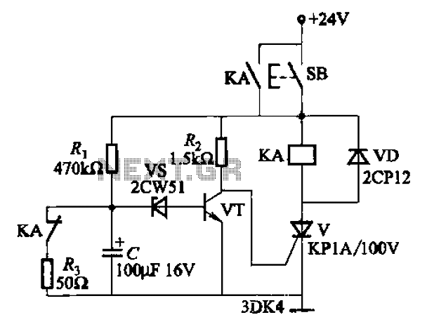
This circuit is a thyristor-based delay circuit known as a cut-off delay. It allows for a specified delay period after the thyristor is activated. The delay time of the circuit can be adjusted within 10 seconds by changing the...
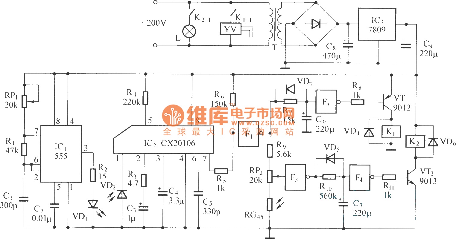
The circuit consists of the following components: (1) An infrared emitter which utilizes a multi-harmonic oscillator based on a 555 timer circuit. The oscillation frequency is determined by the values of RP1, R1, and C1, resulting in a frequency...
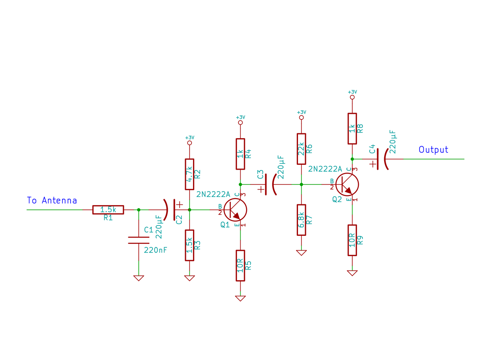
This circuit does not function as effectively as it could. It was created when the designer had a limited understanding of circuit design. An improved schematic will be developed and posted later, featuring a better design. The schematic indicates...
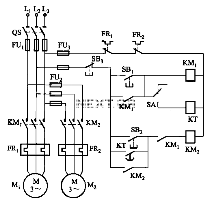
The circuit illustrated in Figure 3-85 features both manual and automatic control through the transfer switch SA. After initiating the motor Mi, an automatic start sequence is achieved via the time relay KT. The circuit employs a transfer switch (SA)...
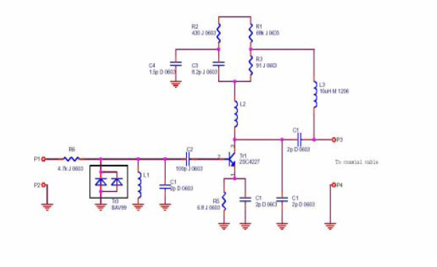
A flat mobile active car antenna is being tested with a Terratec Cinergy DT USB XS Diversity digital tuner. The antenna is designed to enhance signal reception for mobile digital television. The flat mobile active car antenna is engineered to...
This simple flashing light circuit operates at 6 volts and 0.5A, exhibiting low current consumption when the light bulb is turned off. The frequency of the flashing is predetermined. The circuit consists of a power supply, typically a battery or...