
Precision Gated Oscillator Circuit

The circuit described functions as a gated oscillator operating at a frequency of 1 kHz. The primary components involved include resistors R2 and R3, diode D1, and tuning capacitor C1.
In this configuration, R2 and R3 are used to create a voltage divider that sets the reference voltage for the tuning capacitor C1. This configuration allows for precise control over the voltage applied to C1, which is crucial for determining the oscillation characteristics of the circuit. The diode D1 serves to prevent reverse current flow, ensuring that the voltage across C1 remains stable and within the desired range.
The oscillator operates without a long turn-on cycle, which implies that it can quickly reach its stable oscillation state upon activation. This characteristic is beneficial for applications requiring rapid response times. The gating mechanism likely involves a control signal that enables or disables the oscillator, allowing for flexibility in its operation.
Overall, this circuit is suitable for applications where a stable, low-frequency oscillation is required, and the ability to adjust the oscillation characteristics through the tuning capacitor is advantageous. The design emphasizes simplicity and efficiency, making it an effective solution for various electronic applications. A 1-kHz gated oscillator with no long turn-on cycle is show. R2, R3, and D1 preset the voltage on tuning capacitor CI to % of the supply voltage.
Related Circuits
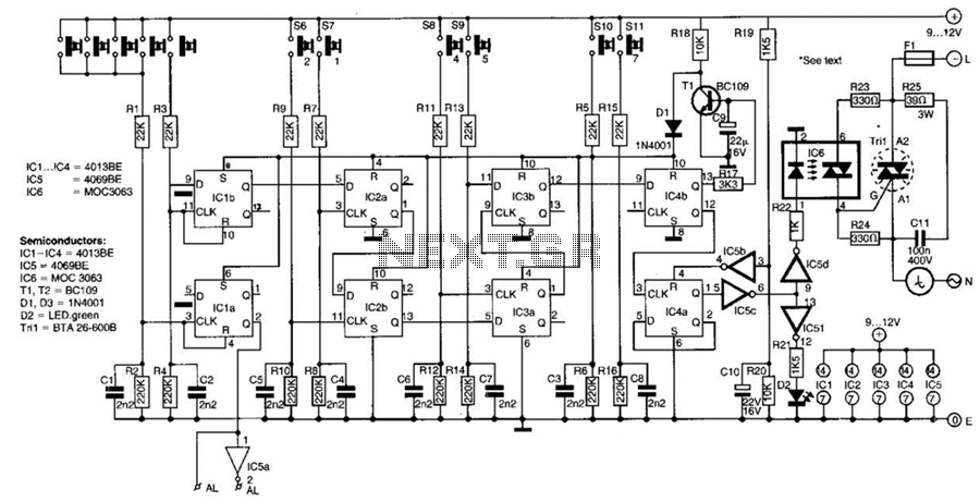
This switch utilizes four CD4013BE dual flip-flops, an inverter, and an optoisolator to control a triac, allowing it to switch a 25-A AC load current. A standard 4x3 telephone keypad is employed for entering a 6-digit code. In the...
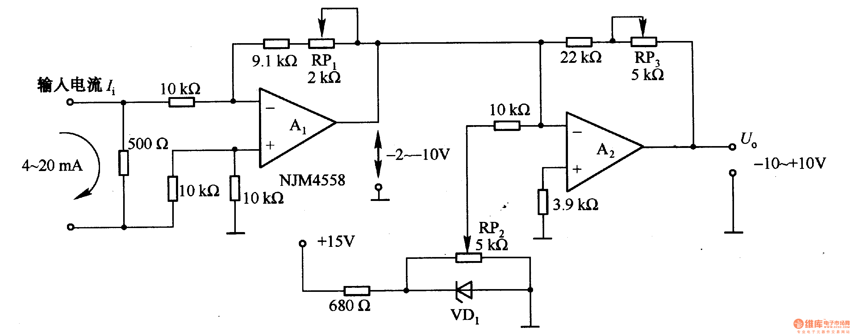
Figure 1-42 (a) is a voltage/current conversion circuit that converts a 0-10V input voltage into a 4-20mA output current. Adjusting resistor RP2 can set the input voltage (Ui) to 0V, resulting in an output current (I) of 20mA; similarly,...
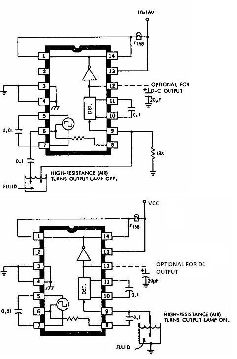
This electronic liquid detector circuit diagram is based on the ULN2429 monolithic bipolar integrated circuit designed for detecting the absence or presence of many different types of liquids. The ULN2429 electronic liquid detector circuit can be used in automotive,...
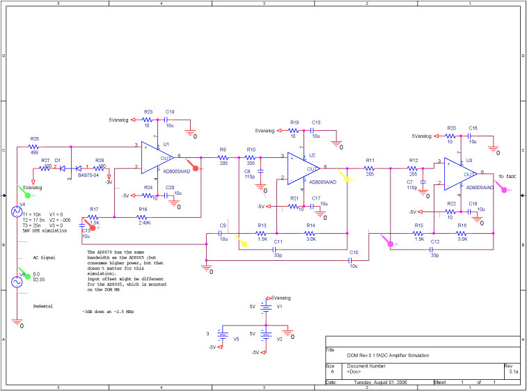
A bandwidth-limited amplifier shapes the waveform sampled by the 40 MHz high-speed pipeline Analog to Digital Converter (fast ADC, or fADC). It is well known that the shaping time is twice the time constant (peaking time) for each pole...
The metal detector circuit comprises several key components, including a power circuit, a sine wave oscillator, a PLL (phase-locked loop) circuit, and a hybrid amplifying circuit. The power circuit is made up of batteries GBI and GB2, filter capacitors...
This project involves a simple circuit designed to mix two or more audio channels into a single channel, such as converting stereo audio into mono. The circuit is capable of accommodating multiple input channels while maintaining low power consumption....