
Principle Power Amplifier Design

SRPP tube preamplifier circuit, as shown in Figure 7-25. Parallel to its circuit-adjusted push-pull circuit, also known as streaming-adjusted push-pull circuit, used for high-frequency input stage, such as VHF / UHF high frequency of the first tube line, and for the importation of AF, both distortion, Linearity, magnification, dynamic and low output impedance are all winners of Group A in general triode amplifier, and many other giant tube circuit design the contrary, SRPP circuit distortion rate decreases as the frequency increased. The circuit is clearly a series of two tubes, how is the parallel-push-pull adjustment circuit This is the exchange of work, two DC power tubes in the form of series, each shoulder half of the supply voltage.
But the exchange does not signal the same pipe above the screen is the very same, enter the pipe from below the screen is, by the cathode output (of screen circuits), this becomes a two tubes in parallel work. Because the gate is on the tube for a relatively cathode negative circumstances, makes bias circuit is extremely simple, this principle can not be used in transistors or operational amplifier circuit.
FET amplifier circuit theory, differential-ranked dynamic principles such as Figure 7-26 shown. Differential input stage a field-effect twin module NPD5565S, its parameters for VDss = 55V, iDss = 6 ~ 15mA, its importation of very good (high input impedance), without the NPD5565S, can also be used other small N-channel power of resistance, Pressure demand is greater than 100 V, Gm value pairs, the error to less than 2 percent. VR is a source of negative feedback resistor is the midpoint potential for zero resistance. VT3, VT4 is a constant source mirror the characteristics of the DC Circuit similar pathway, and in terms of the exchange is open so that we can meet all of the DC work, and it also enabled the exchange as much as possible to send signals to the next level, This class is to promote the best, not because of the traditional midpoint of the ordinary DC servo amplifier circuit, making mid-point of zero potential for a very convenient and simple.
VT5, VT6 to enlarge voltage level, due to the current passion of a circuit-style, R4 decision VT5, VT6 current size of the work, the conditioning R4, so that VT5, VT6 the work of current 80 mA, work in the Group A state, on the one hand can be eliminated The reference to the terrible distortion, and it will strengthen the capacity of the load. If the midpoint of potential instability but transferred to 0. 1 (that is, the midpoint of drift), then R6 can reduce the resistance by 6. 8 kohm or 4. 7 kohm, but resistance can not be less than 4. 7 kohm, and the casual VT3 ~ VT6 Large enough area to heat. Amp-class principle as shown in Figure 7-27, and promote after-class level and the coupling between the abolition of the traditional capacitive coupling, power amplification of a bipolar FET FET, the lines per channel for the four pairs, parallel Use, reducing output damping.
This line output power of 50 W, enough to enjoy the dynamic music. Per channel for the four pairs, if matching more difficult, may be two pairs, matching the requirements of error of less than 3 percent. The use of mica insulation, thermal conductivity and painted Guizhi. The gate of the power of resistance used colored ring 1 / 4 W metal film resistors. Resistance is, the more sounds "warm", the test in the 330 ohm to 470 ohm between for the best. Absorption circuit in the value of R and C can not be too small, can not. Power transformers used 600 W Central transformer, such as E-type transformers are better, and to promote class-amp and power per channel to separate independent.
🔗 External reference
Related Circuits

The 60-watt linear amplifier is a straightforward all-solid-state circuit utilizing the power MOSFET IRF840. The IRF series of power transistors is available in various voltage and power ratings, with a single IRF840 capable of handling a maximum power output...
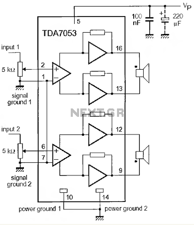
This is a 1-watt stereo audio amplifier circuit utilizing the TDA 7053 integrated circuit from Philips. It is specifically designed for battery operation, delivering 1 watt per channel from a 6V DC supply. The circuit operates optimally between 6V...
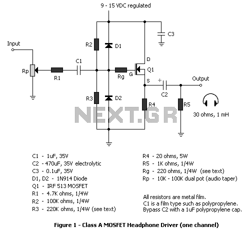
The circuit described in this article is a MOSFET follower for driving headphones. FET followers can supply high current, but have a voltage gain of slightly less than unity. They are most suitable in applications where the input signal...
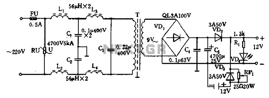
12V DC power supply circuit. A typical 12V DC power supply circuit includes a transformer that converts mains voltage to the required 12V AC output. It features a full-wave rectifier and a capacitor filter. The circuit typically incorporates a...
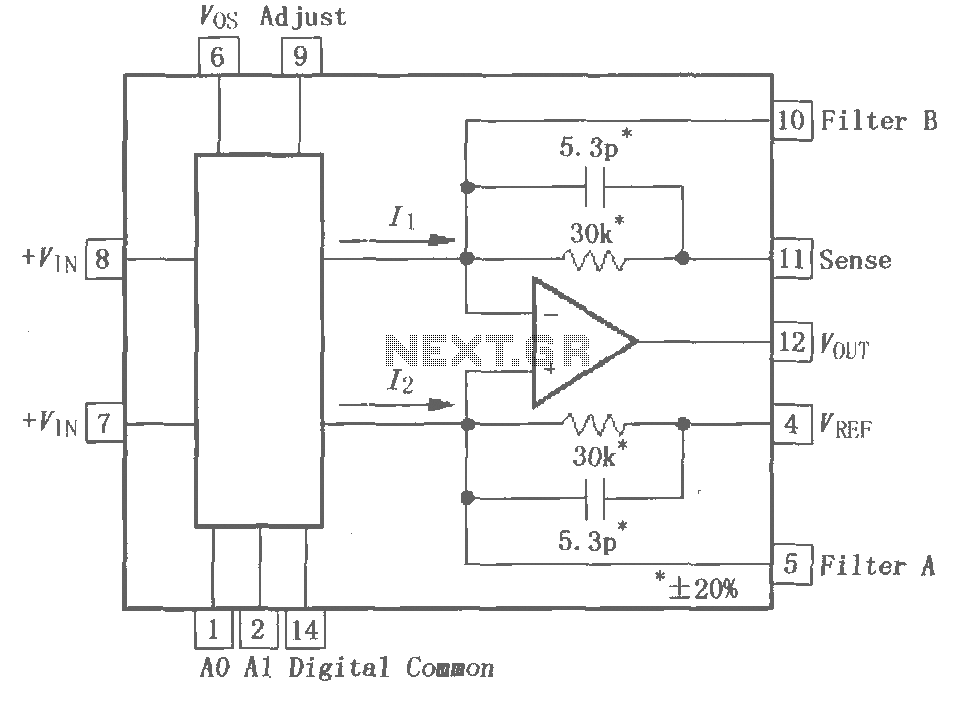
The PGA202 is a digitally controlled programmable gain amplifier with gain settings of G = 1, 10, 100, and 1000. The PGA203 offers gain settings of G = 1, 2, 4, and 8. Both amplifiers are compatible with CMOS...
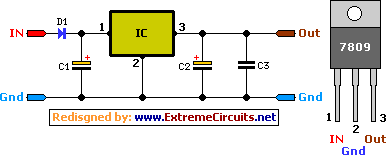
This circuit primarily relies on a voltage regulator. The 7809 voltage regulator can provide a continuous output of up to 2 amps while ensuring a low noise and highly regulated supply. Although the circuit can function without additional components,...