
12V DC power supply circuit

The 12V DC power supply circuit is designed to convert high-voltage AC mains into a stable low-voltage DC output suitable for various electronic applications. The transformer steps down the AC voltage to 12V, which is then rectified by a full-wave rectifier, typically using four diodes arranged in a bridge configuration. This rectification process converts the AC voltage into pulsating DC voltage.
The capacitor filter smooths the pulsating DC output from the rectifier, reducing ripple voltage and providing a more stable DC level. The output capacitor's value is critical; it must be sufficiently large to ensure that the output voltage remains stable during load variations.
The series pass transistor regulator, often configured with a bipolar junction transistor (BJT) or a MOSFET, regulates the output voltage by varying the resistance based on the feedback from the output. The feedback mechanism ensures that the output voltage remains constant despite changes in load or input voltage.
The diode connected in parallel with the capacitor serves a dual purpose: it protects the transistor from voltage spikes and reduces the peak voltage that could otherwise damage the transistor. This diode also helps to minimize hum modulation by providing a discharge path for the capacitor when the load fluctuates.
Capacitor C6 plays a significant role in enhancing the stability and response time of the regulator circuit. When there is a change in output voltage (Uo), C6 allows for a gradual change due to its charge and discharge characteristics. This gradual change prevents sudden spikes in voltage at the base of the transistor VT2, which could lead to instability. By smoothing the voltage transitions, capacitor C6 ensures that the control mechanism of the transistor remains effective, thereby stabilizing the output voltage further and enhancing the overall performance of the power supply circuit.
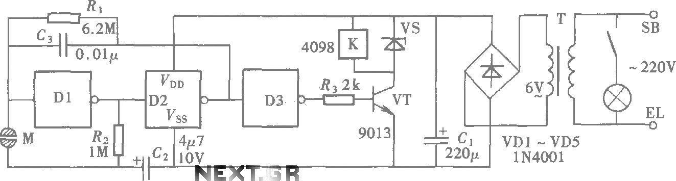
In summary, this 12V DC power supply circuit is a well-designed system that incorporates essential components for voltage conversion, rectification, filtering, and regulation, making it suitable for powering various electronic devices reliably.12V DC power supply circuit A typical 1V DC power supply circuit as shown in FIG. The figure for the power supply transformer Tr, which the mains voltage to the required two gr oups of 1V AC low. Rectifier full wave rectifier, capacitor filter mode. Regulators are typically part of a complex series pass transistor regulator circuit, the whole figure has O.OIpF diode in parallel across a capacitor, its role is to reduce the rectified peak voltage of the transistor, and to avoid hum modulation. The role of the capacitor C6 is to increase the ability to control, since it is assumed when the output is - change Uo of, if not add capacitor C6, then the amount of change is Rs, where after Rw and partial pressure applied to VT2 tube base; and plus a capacitor C6, due to the voltage across the capacitor voltage can not change suddenly, so that the entire amount of change will be applied to the base of the pole tube VT2, improve the ability to control, to further stabilize the output voltage.
Related Circuits
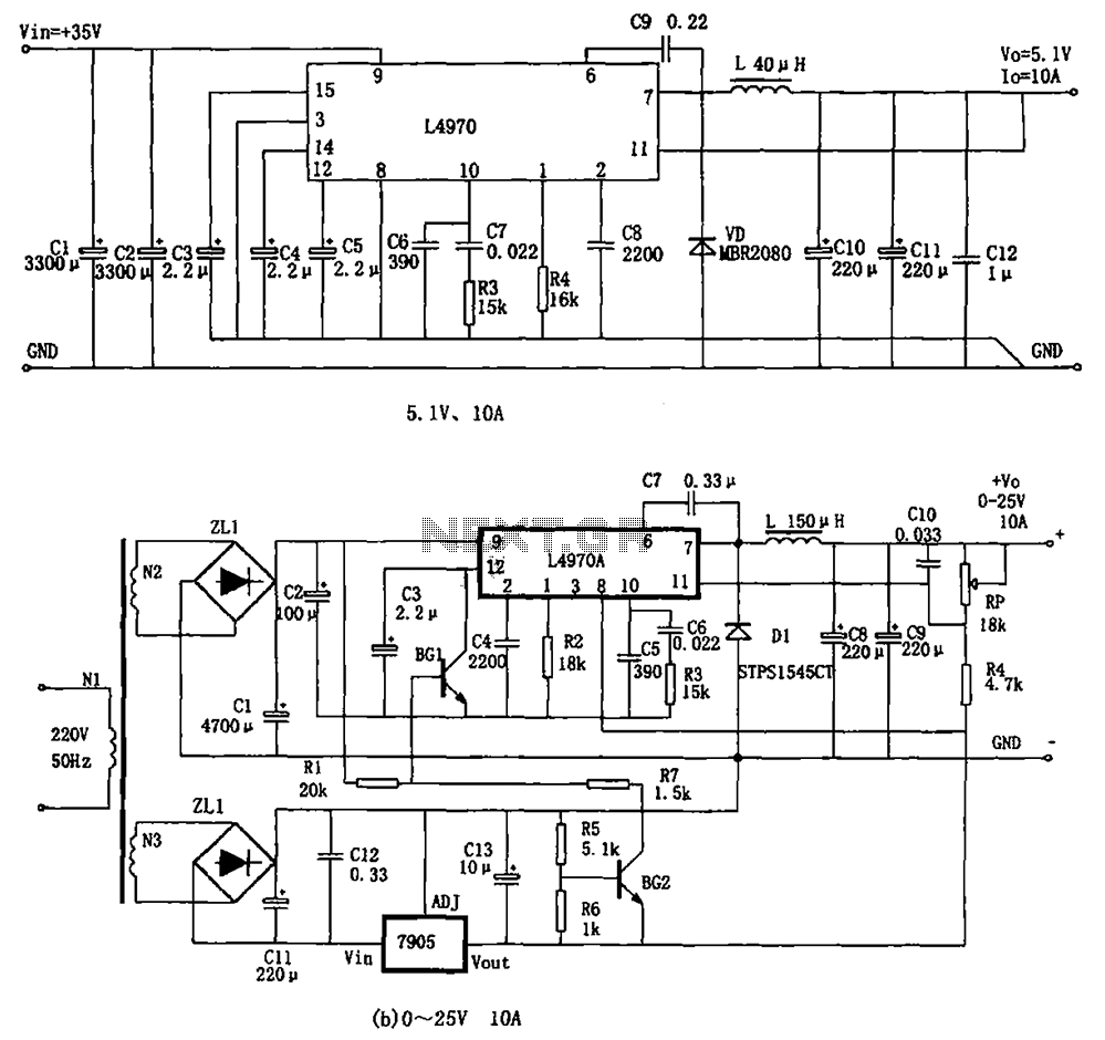
The L4970A power switching supply is a high-power monolithic integrated switching regulator, packaged in a SIP-15 format. It has specific characteristics: (1) The input voltage must be at least 11V, typically ranging from 15V to 40V; (2) The output...
A highly effective 1-watt FM transmitter circuit that is easy to construct. The circuit consists of four transistors: one functions as a stable oscillator, followed by a buffer stage to maintain frequency stability during adjustments. Next is a resonance...
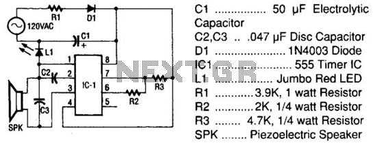
The tester comprises a rectifier circuit and a multivibrator circuit. The alternating current (AC) voltage is half-wave rectified by diode D1 and stored in capacitor C1. Resistor R1 is employed to limit the current through D1 to a safe...
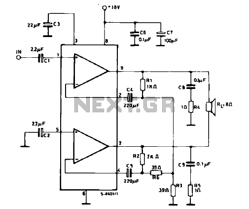
The schematic illustrates a 12 W Bridge Amplifier circuit diagram utilizing the TDA2007A, a class AB dual audio power amplifier. This amplifier is specifically designed for stereo applications in music centers, television receivers, and portable radios. As stated in...
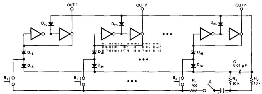
This switching circuit functions as a bank of interlocked mechanical switches. Activating one of the buttons latches its corresponding output while unlatching a previously selected output. A pair of inverters creates a latch for each output. For instance, pressing...
A CMOS gate exhibits high input impedance, which allows it to respond to changes in input levels due to human contact, thereby triggering the toggling of gates. The circuit utilizes this characteristic to create a touch lamp switch. The...