
Privacy in parallel telephone line

The described circuit involves a dual telephone setup utilizing a Double Pole Double Throw (DPDT) switch configuration to facilitate the connection of two telephone instruments to a single telephone line while preventing issues such as overloading and unauthorized overhearing of conversations. The system operates by allowing only one telephone to be connected to the line at any given time, thus ensuring clear communication.
In this setup, each telephone instrument is equipped with a DPDT toggle switch. The switch has three positions: one connecting the telephone to the line, another disconnecting it, and a third position that can be used for other functionalities or simply to ensure the switch is not inadvertently activated. The DPDT switch effectively isolates the communication path, allowing for seamless switching between the two telephones.
To implement this system, two wooden switchboards are required. Each board is equipped with a DPDT toggle switch, a telephone ringer, and a telephone terminal box. The telephone ringer serves to signal incoming calls, ensuring that both instruments are alerted regardless of which is connected to the line at the time. The telephone terminal box provides a secure and organized point for connecting the telephone line to the switches and instruments.
Interconnection between the two boards is achieved using a 4-pair telephone cable, which allows for the necessary wiring to be managed efficiently. It is crucial to ensure that the lower leads of switch S2 are connected to switch S1 after reversal, as this configuration ensures proper functionality and prevents any potential conflicts in the switching operation.
Once assembled and wired correctly, the system allows either telephone to receive calls by simply toggling the switch to connect to the line. This design not only simplifies the user experience but also enhances the overall performance of the telephone instruments by eliminating common issues associated with parallel connections. The result is a reliable and user-friendly solution for managing two telephones on a single line.Often a need arises for connection of two telephone instruments in parallel to one line. But it creates quite a few problems in their proper performance, such as overloading and overhearing of the conversation by an undesired person. In order to eliminate all such problems and get a clear reception, a simple scheme is presented here (Fig.
1). This system will enable the incoming ring to be heard at both the ends. The DPDT switch, installed with each of the parallel telephones, connects you to the line in one position of the switch and disconnects you in the other position of the switch. At any one time, only one telephone is connected to the line. To receive a call at an end where the instrument is not connected to the line, you just have to flip the toggle switch at your end to receive the call, and act as usual to have a conversation. As soon as the position of the toggle switch is changed, the line gets transferred to the other telephone instrument.
Mount one DPDT toggle switch, one telephone ringer, and one telephone terminal box on two wooden electrical switchboards, as shown in Fig. 3. Interconnect the boards using a 4-pair telephone cable as per Fig. 1. The system is ready to use. Ensure that the two lower leads of switch S2 are connected to switch S1 after reversal, as shown in the figure.
🔗 External reference
Related Circuits
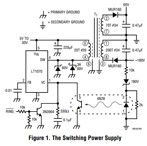
Here is a design that you can own, tailor to your specific needs, layout on your circuit board and put on your bill of materials. Finally, you will be in control of the black magic (and high voltages) of...
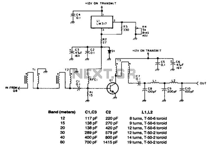
This linear amplifier provides a 10-W PEP output with a 1.25-W drive on the 10 m band. The transformers, T1, T2, and T3, consist of 10 turns of bifilar windings on an FT-50-43 toroidal core and are designed for...
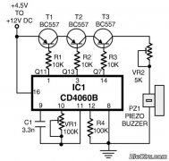
This is a simple home telephone ringtone generator circuit constructed using only a few electronic components. It generates a simulated telephone ringtone and requires a DC supply voltage ranging from 4.5V to 12V. This circuit can be used in...
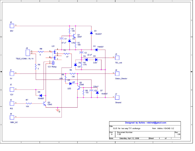
This is a very small telephone exchange connected to two ordinary telephones. It features a fully bi-directional intercom system. When one phone is off-hook, the exchange detects this condition and sends a ringing pulse to the other phone. Once...
This circuit diagram represents a simple yet effective transmitter circuit, capable of transmitting telephone conversations. When the telephone receiver is on the hook, the line voltage is approximately 48 volts. The R7 preset resistor is adjusted to achieve a...
Designing various electronic circuit systems (synthesizer, modem, decoder, data converter, etc.) often requires a frequency modulator subsystem. An FM modulator is a crucial component in these systems. An FM modulator is an electronic device that encodes information in a carrier...