
Two way Simple Very Small Telephone Exchange

The described circuit functions as a compact telephone exchange designed for two standard telephones, facilitating communication between them through an intercom system. The core of this design is the PIC16F84A microcontroller, which handles the logic and control functions necessary for the exchange's operation.
The operation begins when one of the telephones goes off-hook, indicating that the user wishes to initiate a call. The microcontroller detects this status change through the connected SLIC, which interfaces with the telephone line. Upon detection, the microcontroller sends a ringing pulse to the other telephone, alerting the user of an incoming call.
Once the second telephone is picked up, the microcontroller establishes a direct connection between the two phones, allowing for two-way communication. This bi-directional capability ensures that either phone can initiate a call, and the system is designed to handle this interchange seamlessly.
The design incorporates two SLICs, which are essential for interfacing the telephones with the controlling unit. These circuits manage the electrical characteristics of the telephone line, ensuring proper signaling and power delivery. The SLICs must be configured to recognize the status of the telephones, including off-hook and on-hook conditions, and relay this information back to the microcontroller.
In terms of connections, the controlling unit circuit diagram must clearly outline the integration points for the SLICs, the microcontroller, and the telephones. Proper identification of these connections is crucial for the successful implementation of the project. The design should also consider any necessary resistors, capacitors, and other passive components that may be required for stability and performance.
Overall, the circuit represents a practical application of microcontroller technology in telecommunications, providing a simple yet effective solution for direct phone-to-phone communication in a compact form factor.This is a very small telephone exchange attached only two ordinary Tele phones. Fully bi-directional facility with an intercom system. When a phone is in off hook condition, Exchange will detect it & send ringing pulse to other phone. When it will be picked up, the connection will be established between both phones. This will be taken place vice -versa. This circuit is base on PIC16F84A microcontroller. Two slimier SLIC are connected to The controlling unit. It needs to identify following connections on the controlling unit circuit diagram. This unit is required to detect every status from an usual telephone set for the Controlling circuit ( Exchange ). It interfaces an usual telephone to the controlling circuit. Two slimier SLIC are required for this project. 🔗 External reference
Related Circuits
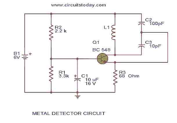
This is the circuit diagram of a low cost metal detector using a single transistor circuit and an old pocket radio. This is nothing but a Colpitts oscillator working in the medium band frequency and a radio tuned to...
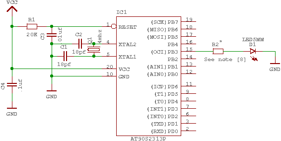
The GNU tools must be configured, built, and installed on the system. This chapter presents a simple example of using the GNU tools in an AVR project. After reviewing this chapter, users should gain a better understanding of how...
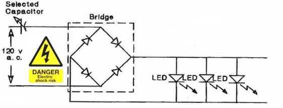
LEDs are great display tools. Their prices have decreased to a point where they are replacing more conventional light sources. In one sense, their characteristic need for low voltages is an advantage, e.g., compatibility with I.C. drives, but this...
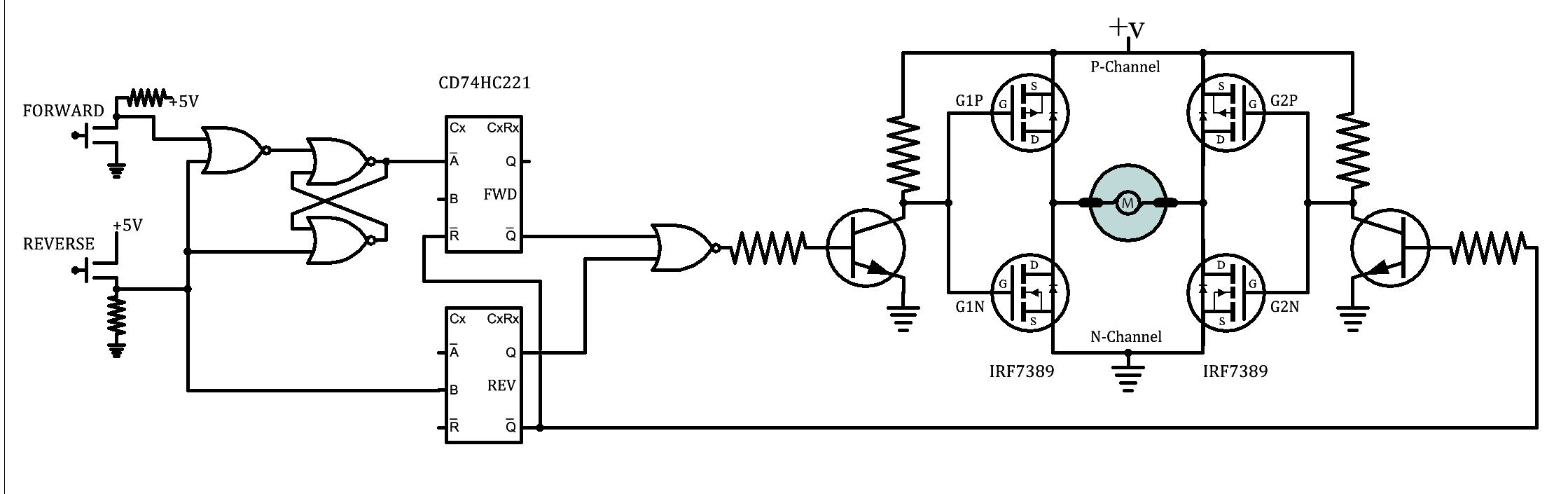
A brief background is provided, indicating a basic understanding of electronics, including knowledge of component functions and schematic reading, but lacking further expertise. The circuit in question appears to involve fundamental electronic components, which may include resistors, capacitors, diodes, transistors,...
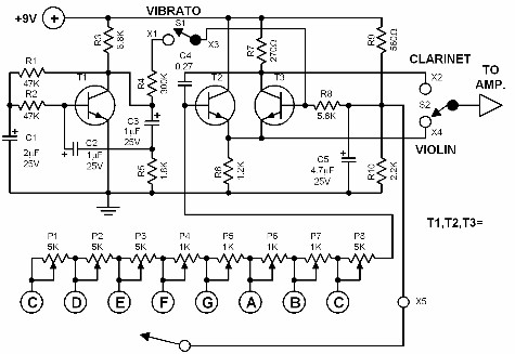
This electronic organ is simple to construct and can provide hours of enjoyment, particularly for children. The circuit is fundamentally an emitter-coupled oscillator consisting of transistors T2 and T3. A square wave voltage can be sampled from the collector...
The preamp circuit is completely conventional, and by necessity is AC coupled throughout. The artificial earth is derived by two resistors (R1 and R2), which will set the "earth" at exactly 1/2 the supply voltage. This is nominally 13.8V...