
Programmable Timer of timer circuit

The programmable timer circuit typically consists of two primary integrated circuits: a timer IC, such as the NE555 or its variants, and a microcontroller or a second timer IC for added functionality. The NE555 timer can be configured in either monostable or astable mode, allowing for versatile timing applications.
In monostable mode, the timer generates a single pulse of a specified duration when triggered. This is useful for applications requiring a delay or a timed event. The duration of the pulse can be adjusted by changing the resistor and capacitor values connected to the timer IC.
In astable mode, the NE555 functions as an oscillator, producing a continuous square wave output. This mode is ideal for generating clock pulses, flashing LEDs, or driving other timing circuits. The frequency and duty cycle of the output waveform can be modified by altering the resistor and capacitor values in the circuit.
The second IC can serve various purposes, such as enhancing the timer's capabilities or providing additional features like programmable intervals. A microcontroller can be programmed to control the timing functions and provide user interfaces, such as buttons or displays, for setting the timer duration and mode.
The circuit design should include power supply considerations, typically using a regulated voltage source suitable for the chosen ICs. Proper decoupling capacitors should be placed near the power pins of the ICs to ensure stable operation.
Overall, the programmable timer circuit is a versatile and essential component in various electronic projects, ranging from simple timers to complex automation systems. Its simplicity and adaptability make it an excellent choice for both beginners and experienced engineers in the field of electronics.Programmable Timer in this website is very simple made from only 2 iC of wide range circuit and description of programmable timer various timer project. 🔗 External reference
Related Circuits
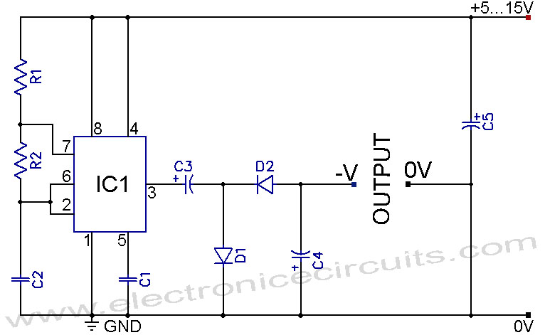
A 555 negative voltage power supply circuit can be created using a charge-pump configuration that incorporates a 555 timer, diodes, and additional components. The 555 timer is a versatile integrated circuit commonly used in various applications, including oscillators, timers, and...
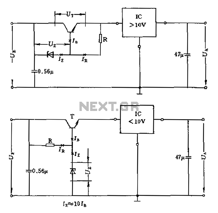
The voltage equation Ue = Ut + Ur + Ua indicates that the transistor voltage Ut will determine the maximum output voltage Ua. Additionally, Ur must be 2V. The voltage regulator's voltage value depends on the selection of Uz....
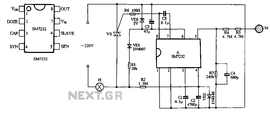
The core component of the circuit is the dimmer, utilizing the SM7232 integrated circuit. The pin configuration includes: 1) VDD, the positive power supply terminal; 2) DOZE; 3) CAP; 4) SYN, which synchronizes input power frequency using an internal...
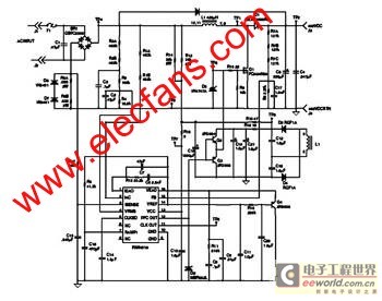
The FAN4810 operates as a continuous conduction mode (CCM) power factor correction (PFC) controller. It features an internal safety detection mechanism that prevents circuit malfunction due to component damage. The device has a power-handling capability of up to 1A,...
It is essentially a standard Hartley oscillator, with an output of +7 dBm into 50 Ohms. It is advised against adding a gate diode, as this circuit does not require it and such an addition would degrade phase noise...
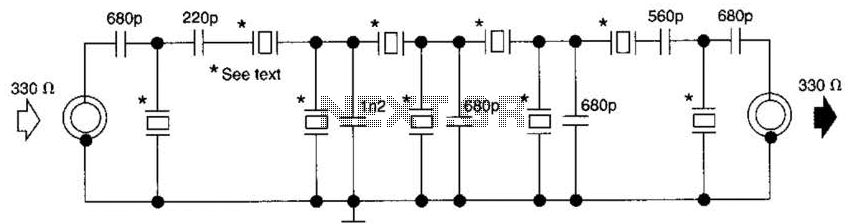
This filter utilizes five 455-kHz ceramic resonators. The impedance is 330 ohms, the bandwidth is 800 Hz, and the ultimate rejection is greater than 60 dB. Additionally, the ceramic resonators can be substituted with crystals. The described filter is a...