
prop clock

The motor assembly features a secondary coil consisting of 200 turns of 28-gauge copper wire, wrapped in electrical tape. An infrared sensor is positioned at the center of the secondary coil to enable mode changes. Additionally, a visible light-sensitive sensor is mounted close to the spindle's center using hot glue. The primary coil is placed above the secondary coil and is partially wrapped in electrical tape to enhance cooling, although it only becomes slightly warm during operation.
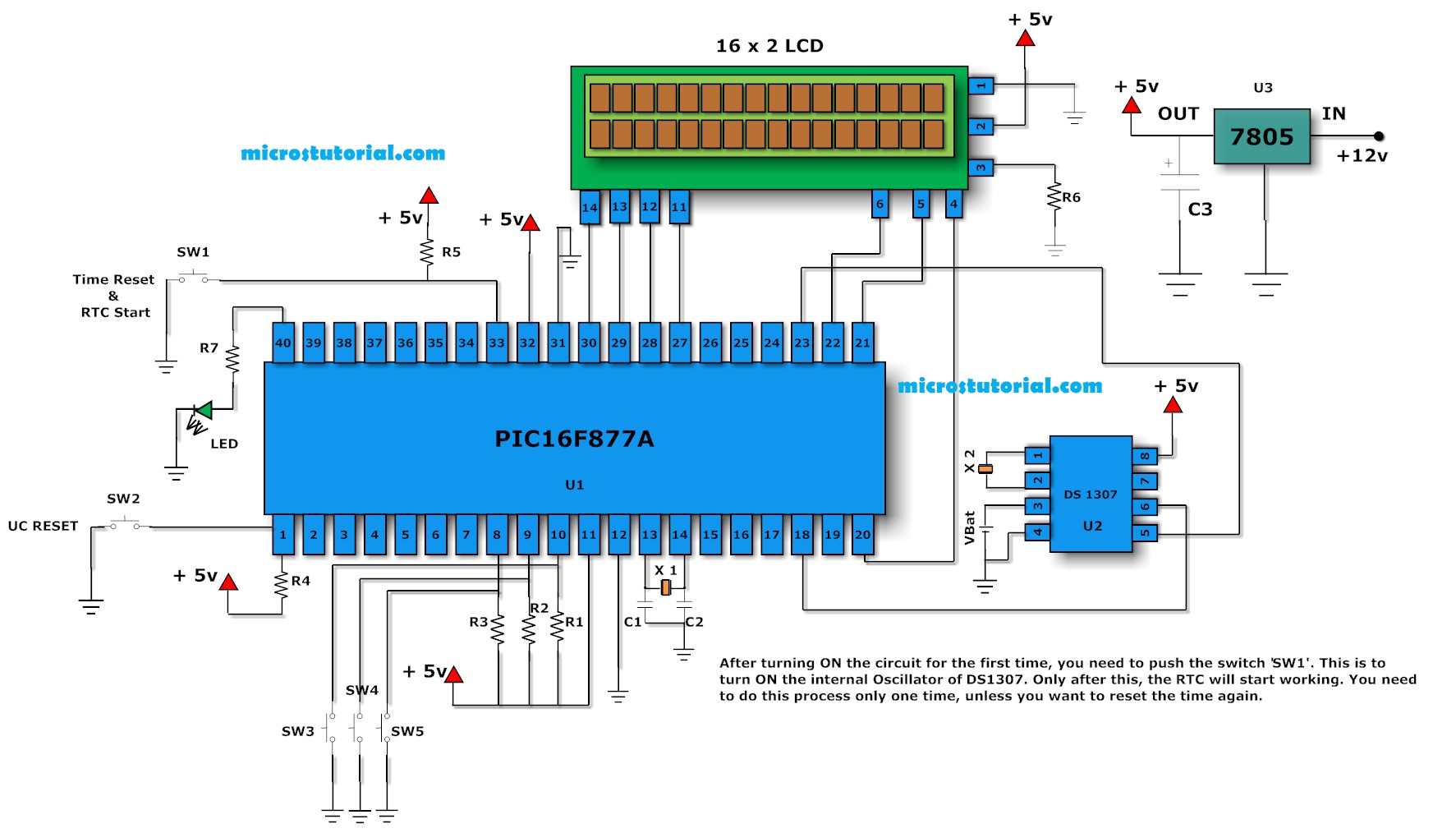
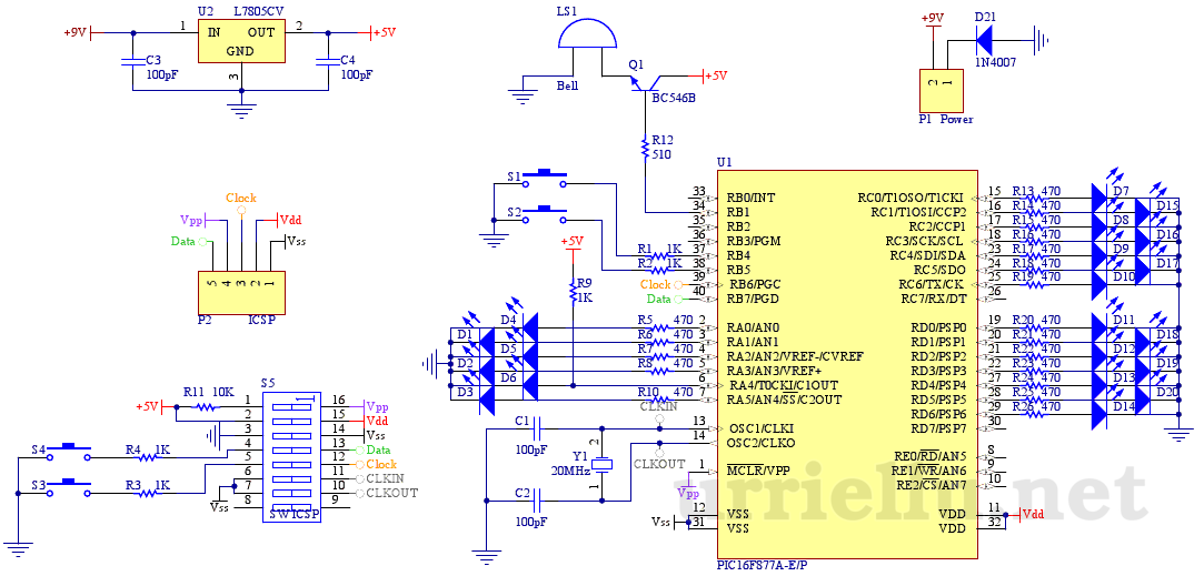
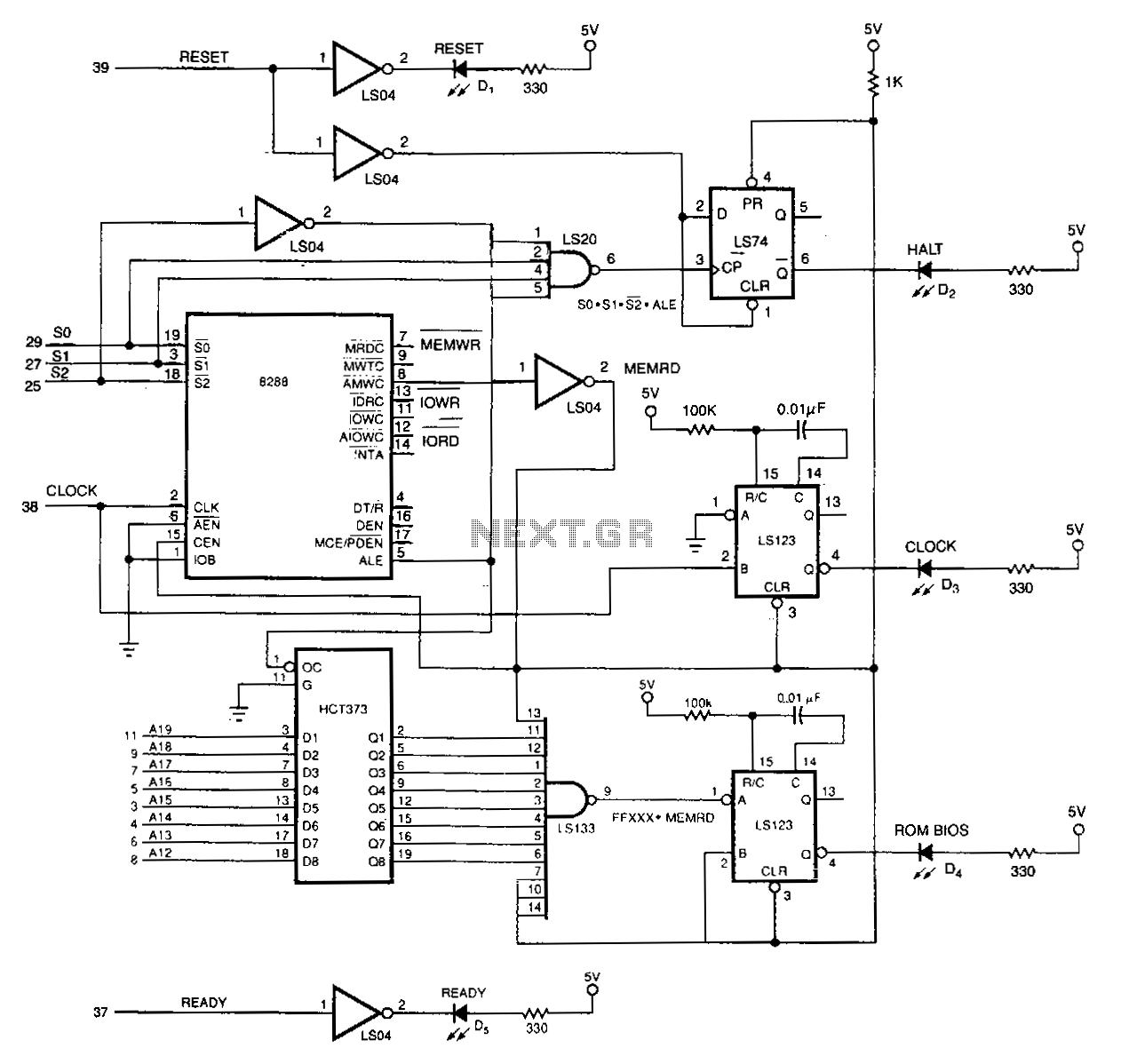
The design includes a triangular acrylic spacer, held in place by aluminum spacers, which supports the primary drive coil, the infrared LED, and a red LED used for mode and time adjustments while the clock spins. The schematic illustrates the clock's design, including the stationary components, which feature a pulse width modulator circuit for speed control and an H-bridge circuit for reversing the polarity of signals to the motor coils. There is also a separate circuit dedicated to pulsing the main drive coil.
The construction of the first clock served primarily as a test to ensure functionality and resolve any issues before proceeding with a second unit.
The detailed schematic provides insights into the layout and operation of the clock, including the placement of the secondary transformer, mode, and time sensors on the motor's rear side. Caution is advised when attempting to print the schematic, as the holes may be too close together. A link to the PDF used for the PCB design is available, although the quality may not be optimal.
This comprehensive overview highlights the intricate design and operational principles of the propclock, showcasing the integration of various electronic components to achieve its unique functionality.Propclocks are really pretty complex devices, utilizing a PIC microcomputer that performs instructions at 10mhz. The PIC is the brain of the device and does most of the work involved in making the LEDs light up at just the right time so that it appears there are numbers, and in the analog mode hands suspened in mid air.
On my version of the clock you change the mode and time setting while it is still spinning at about 1150 PRM. This is done through carefully alligned photo detectors and LEDs. These sensors are located on the rear of the spinning motor so they dont affect the look of the clock at all. (the below diagram should explain it) This is a link to the diagram i made, it shows how the whole thing works, and what makes my clock different from anyone elses i have seen sofar.
(you better like that diagram cuz it took me about 5 hours to make :) Here is an actuall photograph of the backside of the motor assembly. You can clearly see the standoffs and the acrylic stand for the coils and stuff, what you can also see in this picture is the secondary coil which is 200 turns of 28 gua copper wire, its the black thing wraped in electrical tape.
Sticking our from the center of the secondary is the IR sensor which is used for changing the mode. The other sensor that is only sensitive to visible light was also mounted as close to the center of the spindle as possible with hot glue. Also the primary coil is located above it, i only wraped it in electrical tape in 3 spots because i thought this would improve cooling.
It only gets slightly warm though so this probably wasnt needed. Here is a scann of the back of the clock, yess i actually layed the whole thing down on the bed of the scanner :). The barely visible acrylic triangle is spaced from the back of the motor with aluminum spacers, it has the primary of the drive coil hot glued to it, along with the IR led and red led used to change the mode and time settings of the clock while it is spinnning at around 1150 rpm.
This is a digital photo of the front, i had to put white paper behind the clock because the camera wouldnt take good pictures of it with a black backdrop (the black acrylic sheet) Here is the schematic of the clock and the rotating part of the transfomer. In my version of the clock the secondary of transformer, mode and time sensors were all located on the rear side of the motor.
This diagram should help explain it all WANING! this. pdf got screwed up and the holes are to close together when it is printed. I will try to fix this as soon as possible. you can still view it and stuff, just dont try to make a pcb from it Here is a link to the actual. pdf file that i used to make my pcb, its 436kb but the quality isnt really the best, but its as good as i could manage to get it ! (I spent a very long time fiddeling with the file just to get the quality this good !) Here is the schematic for the stationary part of the clock.
It has a pulse width modulator circuit to controll the speed of the clock and a H bridge circuit to reverse the polarity of the signals going to the motor coils. It also has a seperate circuit for pulsing the main drive coil. Here is a photo of construction of my first clock, yess i did build two. The first one was mostly a test to make sure that it would all work right, and to work out all the kinks there always are in new projects.
This way when i built the second one i had the board almost un 🔗 External reference
Related Circuits
The Multimeter Clock consists of three multimeters, the first meter displays hours, the second displays minutes and the last displays seconds. A 16F628A PIC microcontroller keeps track of time and outputs a calculated current to each meter to display...
One of the main problems faced with an ordinary digital clock made using the PIC16F84 (or any other microcontrollers) is that it cannot maintain accurate time during power failures. When power fluctuations occur, the clock resets and starts counting...
This is the first electronic circuit designed from scratch, marking the initial experience with programming a microcontroller (MCU), the first application written in assembly language, and the second homemade printed circuit board (PCB). While it is common for individuals...
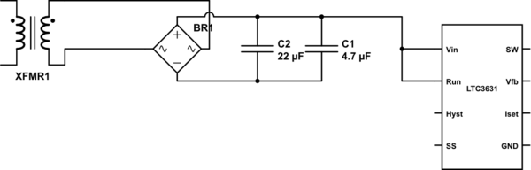
The leads from the transformer to the circuit are quite long (>5m). The 110V side of the transformer has been switched off frequently, which likely caused a spike on the secondary (24V) side. The input pin of the LTC3631...
The 20-MHz clock is phase-locked to the 10-MHz NuBus clock of Apple's Mac II. It employs simple and cost-effective CMOS circuitry to generate square waves at 10 MHz and 20 MHz. The output duty cycle settings are not affected...
This is a chronological account of a project to design and build a digital clock based on the Arduino open-source architecture, utilizing the ATMEGA8 microcontroller. The ATMEGA8 is an 8-bit, 16MHz microcontroller with integrated digital and analog inputs and...