
Protecting Microcontroller Input Pins from Soft Power Switch

The soft power switch circuit for the microcontroller is designed to facilitate an efficient power management system, ensuring that the microcontroller operates only when necessary and conserves battery life. The use of a lithium-ion battery provides a stable voltage range conducive to powering both the regulator and the microcontroller. The TC1015 voltage regulator is chosen for its low dropout voltage, making it suitable for battery-powered applications.
The implementation of a flip-flop adds robustness to the circuit. The flip-flop acts as a memory element that retains the state of the power switch, ensuring that the microcontroller can reliably detect switch presses without being affected by mechanical bounce. The initial button press activates the regulator, and the microcontroller can maintain its operation by setting the uC Power high. This design minimizes the risk of unintended resets or power cycling due to noise or bounce.
To address the potential issue of battery voltage exceeding the microcontroller's maximum I/O pin voltage, a resistor is used on the CLOCK line to limit current and protect the microcontroller. This resistor ensures that when the CLOCK line is driven high, the voltage does not exceed safe operating levels for the microcontroller.
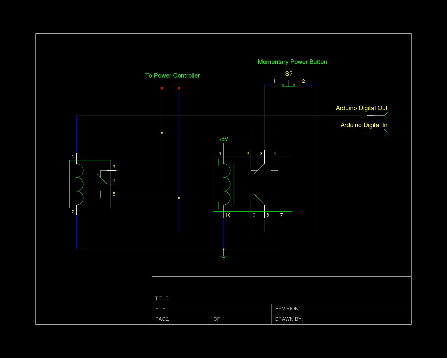
The circuit's design also considers power consumption. The use of pulldown resistors and the flip-flop configuration minimizes current draw during the off state, which is critical for extending battery life. Overall, this soft power switch circuit is a well-thought-out approach to managing power in microcontroller applications, balancing functionality with efficiency and reliability.Soft power switch for a microcontroller where a momentary switch can turn the circuit on (including microcontroller), and then when the switch is pushed a second time, the microcontroller can shut itself off after performing some clean up. I have the above circuit so far, but I`m not sure if it`ll be reliable. I`m using a lithium- ion battery (3. 7-4. 2V) and the TC1015 regulator (3. 0V output). The idea is that when the switch is pressed, the regulator turns on, then the microcontroller sets uC Power high, keeping itself on. When the switch is pressed a second time, an interrupt on uC Switch will allow the microcontroller to set uC Power low, turning itself off.
What I`m not sure about, is if I need to protect the microcontroller from battery voltage. The microcontroller I`m using has an absolute maximum voltage on the I/O pins of Vdd+0. 4V, so I`m not sure how to handle that best. Second, will this circuit actually keep the regulator from turning on when it`s in the "off" state I had thought about using a pulldown resistor on the enable line, but am worried about the current draw while the chip is powered on. The new circuit uses a flip flop, with the data line normally pulled low. Pressing the switch hits the clock, turning the system on. Subsequent presses of the switch drive the CLOCK line high (allowing the microcontroller to sense the press), but don`t affect the output of the regulator.
Once the microcontroller is ready to power off, it sets the DATA line high and then sets the CLOCK line high, which will cause the regulator to shut down. One of the really nice things about this setup, is that the first button press turns the regulator on, and keeps it on until the microcontroller is ready to shut down.
Bounce isn`t an issue, because no matter how many times the clock line goes high, the data line is still held low by the pull down. In addition, the current draw should be very minimal (just the flip flop and the TC1015 while off), and there is minimal current draw through resistors while on.
The microcontroller does need to be protected from the battery voltage on the clock line, but as @Andy aka suggested, that can be done with a resistor on CLOCK. 🔗 External reference
Related Circuits
A charger is essential for charging a 12 Volt battery from a 12 Volt source due to the typical voltage variation between 11 Volt and 15 Volt. A battery requires a controlled charge current and voltage, which cannot be...
When working with electronics, you always need one basic thing; power. This power supply is great for powering all kinds of electronic projects. It produces a well filtered, variable 1.2-30 volts at 5 amps. It is easy to build...
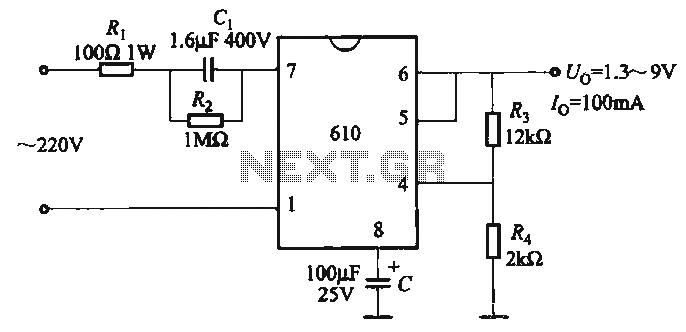
The output voltage can be calculated as follows: U = 1.3 (1 + R3 / R4) (V), where R3 and R4 are part of an adjustment potentiometer, allowing for a continuously adjustable output voltage. The described circuit involves a voltage...
Power supplies: Linear or SMPS (Switched Mode). A distinction is made between linear and switch mode power supplies. What is the difference? A power supply fundamentally is an... Power supplies are essential components in electronic circuits, providing the necessary voltage...
The power controller module in the system receives input directly from a momentary switch and utilizes this input to toggle a relay, which supplies mains power to the system's transformers. The controller circuit operates at 12V, a choice made...
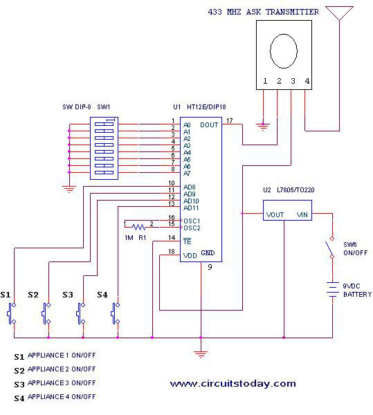
This project outlines a simple remote control system utilizing RF communication without the use of a microcontroller. The remote is designed for various home appliances such as televisions, fans, and lights, providing significant convenience by allowing operation from a...