
Remote Control Circuit Through RF Without Microcontroller

In the remote section, an encoder (HT12E) and an ASK transmitter are integrated. The encoder generates an 8-bit address and 4-bit data, with the address set using a DIP switch connected to pins A0 to A7 (pins 1 to 8) on the encoder. It is essential to configure the same address on both the transmitter and receiver sections. Upon pressing any key on the remote, the encoder produces the corresponding 4-bit data, which is transmitted along with the 8-bit address via the ASK transmitter. The transmitting frequency is 433 MHz, with an output power of up to 8 mW at 433.92 MHz, achieving a range of approximately 400 feet in open areas and around 200 feet indoors.
The receiver section incorporates an ASK receiver operating at the same frequency of 433.92 MHz, featuring a sensitivity of 3 µV. This receiver operates within a voltage range of 4.5 to 5.5 volts DC and provides both linear and digital outputs. It receives data from the transmitter, which is then decoded by the HT12D decoder. The decoder activates the corresponding output pins (pins 10, 11, 12, and 13), each connected to separate flip-flops. The output from the encoder alters the state of the flip-flop, changing its output from a low (reset) to a high (set) state, generating a high signal at the flip-flop output.
Since this output signal cannot directly drive a relay, a current driver is employed, utilizing an SL100 transistor. The appliance is connected to the 230V AC supply through the relay, allowing it to be powered on. Pressing the same switch on the remote re-energizes the relay, as the output from the decoder returns to high, changing the flip-flop state once again. Consequently, the relay is re-energized, turning the appliance off.
This remote control system provides an efficient and user-friendly method for managing home appliances wirelessly, leveraging RF technology to enhance convenience in everyday tasks. The integration of encoders, decoders, and flip-flops ensures reliable communication and control, while the use of a current driver facilitates the operation of high-voltage appliances.This is a simple type remote control by using RF communication without microcontroller. In this project a remote has been designed for various home appliances like television, fan, lights, etc. It gives lot of comfort to the user since we can operate it by staying at one place. We can control any of the appliances by using this remote within the r ange of 400 foots. In this project consist of two sections, transmitter (remote) and receiver section. Whenever we are pressing any key in the remote it generates the corresponding RF signals, and these signals are received by the receiver unit. ASK transmitter and receiver is used as transmitter and receiver. HT12E, HT12D encoders and decoders are used in this electronic circuit. The block digram of the whole circuit is given below. In remote section consist of an encoder (HT 12E) and a ASK transmitter. The encoder generates 8 bit address and 4bit data. We can set the address by using the DIP switch connected in A0 to A7 (pin 1 to 8 ) encoder. If we set an address in the remote section, the same address will be required in the receiver section.
So always set same address in transmitter and receiver. Whenever we press any key in the remote the encoder generates corresponding 4bit data and send this data with 8bit address by using ASK transmitter. The transmitting frequency is 433MHz. The transmitter output is up to 8mW at 433. 92MHz with a range of approximately 400 foot (open area) outdoors. Indoors, the range is approximately 200 foot. At the receiver section ASK receiver is present. The receiver also operates at 433. 92MHz, and has a sensitivity of 3uV. The ASK receiver operates from 4. 5 to 5. 5 volts-DC, and has both linear and digital outputs. It receives the datas from the transmitter. Then the decoder (HT 12D) decodes the date and it will enable the corresponding output pin (pin 10, 11, 12, 13).
Each output pins are connected to separate flip flops. The output of encoder will change the state of the flip flop. So its output goes to set (high) from reset (low) state. This change makes a high signal in the output of the flip flop. This output signal is not capable to drive a relay directly. So we are using current driver, SL100 transistor act as the current driver. The appliance is connected to 230V AC through the relay and the appliance will start. The relay will be re-energized when the same switch is pressed in the remote. This is because we are pressing the same switch in the remote control. The output of the decoder again goes to high so this signal will again change the state of the flip flop. So, the relay gets re-energized and the appliance goes to OFF state. 🔗 External reference
Related Circuits
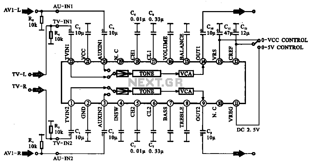
Audio signal control circuit. It illustrates a typical audio signal control circuit where two audio signals enter the integrated circuit through switching and tone controls (treble and bass), subsequently adjusting the output sent to the audio power amplifier. The audio...
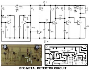
Metal Detector Circuit Overview The metal detector circuit is an electronic circuit that is specifically designed to detect metal that lies deep in the water. The metal detector circuit operates on the principle of electromagnetic induction, where a coil generates...
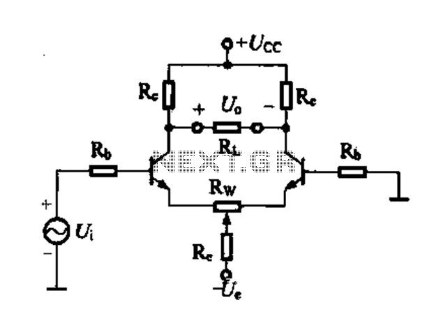
Differential amplifier circuit with four connection methods and characteristics for comparison. The circuit exhibits magnification with a single tube when symmetrical. Additionally, CMRR (Common Mode Rejection Ratio) is adapted from single-ended input to a double-ended output. The differential amplifier is...
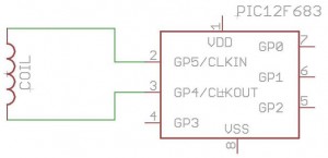
How to build your own RFID system using a microcontroller. This schematic is very simple. Building a Radio Frequency Identification (RFID) system using a microcontroller involves several key components and a straightforward schematic design. The essential elements of an RFID...
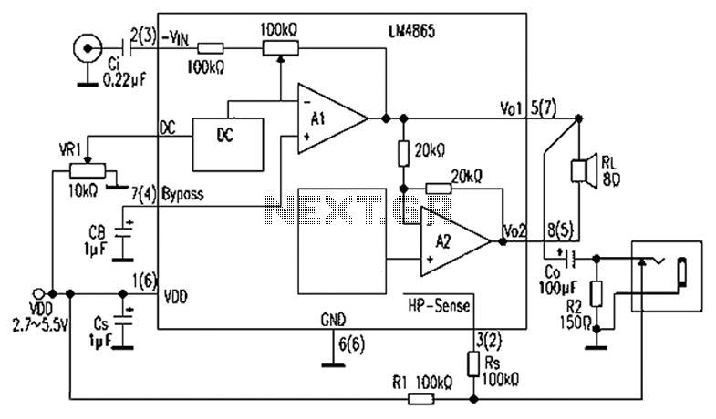
A 750mW bridge-tied load audio amplifier circuit utilizing the LM4065 amplifier is presented below. The LM4865 is available in an 8-pin SO package and an 8-pin mini SMD package. The power supply voltage (VDD) ranges from 2.7V to 5.5V,...
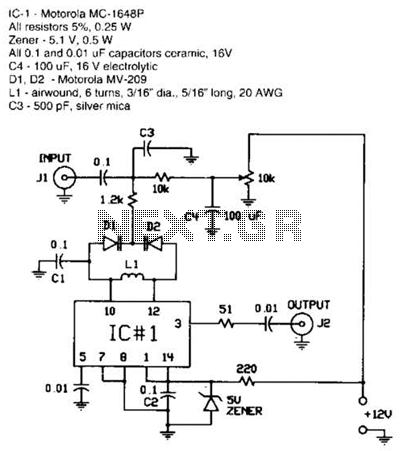
The FM modulator is constructed using a Motorola MC1648P oscillator. Two varactors, the Motorola MV-209, are employed to frequency modulate the oscillator. A 5000-ohm potentiometer is utilized to bias the varactors for optimal linearity. The output frequency, which is...